Converting Engineering Drawing to 3D CAD
What are you supposed to do when you have a 2D engineering drawing but need to incorporate the part into your 3D CAD assembly? You might need to check the fitment, interfaces, and usability of the part, but you can’t start without a 3D model.
It could be a vendor component, COTS item, or legacy drawing that was just never converted to 3D CAD. In this guide, we’ll teach you how to correctly convert engineering drawings into 3D CAD. Our master draftsmen put together this guide to give you quick tips to get the best results and quickly convert 2D drawings into 3D models.
How to Convert Engineering Drawings Into 3D CAD
Here are a few tips to efficiently convert engineering drawings into 3D CAD. All you need is the 2D drawing and access to a 3D CAD program of your choice (these tips work for SolidWorks, PTC Creo, Siemens NX, and CATIA).
Remember Your Three Views
The 2D engineering drawing package you’re looking at will have a series of views on them, each one looking at different faces of the part or assembly. Imagine you’re holding a Rubik’s Cube in your hand. Every time you flip the cube 90° in your hand, you’re looking at a new face — this is exactly what’s happening on the engineering drawing.
Now, imagine you’re holding the drawn component in your hand. As you look at it front-on, you’ll only see the front face. Rotate it 90° in Ry and you’ll see the side view, or 90° in Rx and you’ll see the top view. A lot of designers employ this tactic to keep parts oriented in their mind’s eye.
If the 2D drawing has a top, front, and side view, you’re in luck. As long as each view is fully dimensioned, you have everything you need.
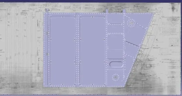
Start by just looking at the drawn front view. By definition, this view should have the most detail, the most dimensions, and be the focus of the part.
On your 3D CAD software, start with a sketch on the XY plane (at the origin). Use the dimensions, features, and shape from the front view on the engineering drawing to this sketch on your 3D CAD program. Your sketch should look just like the 2D drawing, since you’re drawing in 2D right now.
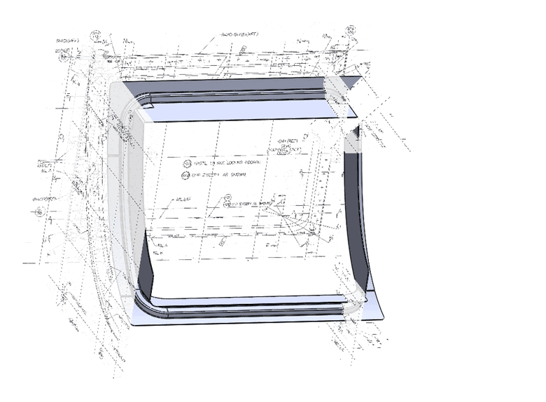
Extrude the front face to the depth shown in either the top or side view.
Next, pick another view and repeat the process, changing the plane. This extrusion will likely cut into the previous extrusion.
Once you draw and extrude the front, top, and side views, your 3D model is basically done.
This is the best practice for making 3D models out of 2D drawings. Tackle it one face at a time, typically starting with the front face.
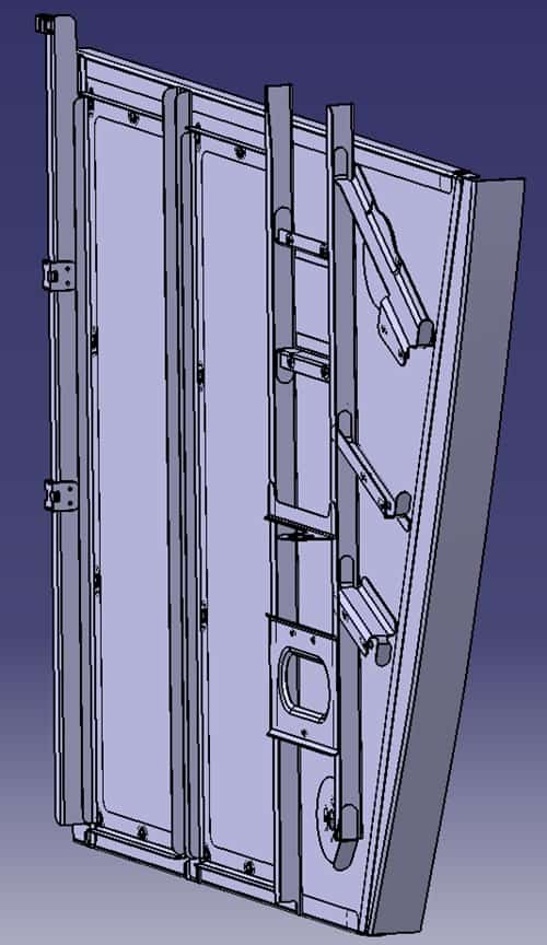
The final steps involve cleaning up the model and handling some smaller details like radii, filets, pockets, and chamfers.
Use the ISO for Reference
We always appreciate an isometric view on an engineering drawing. Even though it isn’t technically required, it can give you a great frame of reference.
They’re especially useful for more complicated parts that have hidden lines everywhere, since the ISO view will help you see how the final part looks.
As you’re making your 3D model, check in on the included isometric view and make sure your model looks like the reference ISO.
For Assemblies, Draw Each Part Separately
If the engineering drawing details an assembly, it doesn’t mean that you have to draw it as an assembly. In fact, most companies’ way of working dictates that you should draw individual parts and assemble them in CAD, rather than drawing a single part as an assembly.
For a simple example, let’s say you receive a 2D engineering drawing of a desk from a vendor. Instead of drawing the legs, tabletop, and supports in a single file, you should create multiple parts.
One file should just be one leg, another file will just be the tabletop, and so on. From there, you can create an assembly model and put all the parts together and constrain them.
Doing this can avoid lots of headaches in the future. If you need to adjust the interface between the legs and tabletop, for example, you can do it within the part file and have your assembly update automatically.
Drawing the full assembly as a single CAD file means that any changes require a lot more work.
Incorporate the Specs
There’s a good chance that your engineering drawings have specs that need to be considered as you make a 3D CAD model. At a minimum, you should include things like:
- Material type
- Tolerances
- Geometric tolerances (flatness, parallelity, concentricity, etc.)
- Surface roughness
- Any finishing steps or treatments
- Paint or powder coating requirements
For your 3D model, these specs will either be a part of the actual model, or they’ll show up in any drawings you make in the future from your model.
Avoid Third-Party Software
There are a lot of companies that offer software that converts 2D drawings into 3D models. It’s not a good idea to try them. For one, the software (that we’ve tried, at least) does a poor job of capturing all the detail. It’s good for models that only have a single extrusion based on one view, but it falls short when multi-view drawings need to be converted.
More importantly, there’s no telling what these companies are doing with your data. If you’re working with classified models or government Top-Secret projects, you can’t afford to leak data. When you willingly upload a 2D model to these sites, they can legally sell the data to the highest bidder.
Instead, use the tips that we outlined earlier to convert a 2D engineering drawing into 3D CAD.
Conclusion
Converting engineering drawings into 3D CAD can be easy, especially with enough practice. Remember to use the three views on the drawing, consider the isometric view for reference, draw each part separately, and incorporate all of the included specs so information isn’t forgotten.
If you’re still lost, don’t worry. You can reach out to our team at CAD / CAM Services, and we’ll take care of converting your engineering drawings into 3D CAD. We’ll sign all the right paperwork to keep your company secrets and IP secure — we don’t use third-party software to convert drawings. Our in-house designers manually convert more than 4 million drawings to 3D models each year.
Recent Posts


Tips for Picking the Perfect 3D CAD Viewer for Your Needs
This guide will teach you about 3D CAD viewers and outline considerations to make before picking the right one. We review 5 options and pick a clear winner.

In this guide, you’ll learn how CAD/CAM Services can save you time and money during each digitization project. Digitization can make manufacturing faster than ever before.

How to Build an Aircraft Model by Converting 3D-Scanned STL Files into Functional 3D STEP Files
This in-depth guide will teach engineers how to use 3D-scanned aircraft files and transform them into manufacturable 3D STEP files with fewer mistakes.