By clicking “Accept All Cookies”, you agree to the storing of cookies on your device to enhance site navigation, analyze site usage, and assist in our marketing efforts. View our Privacy Policy for more information.

Point Cloud to 3D Models

Professional Outsourced Point Cloud to 3D Models Services

3D scanning is a great way to expedite every reverse engineering project, but it comes with a big hurdle: how are you supposed to convert your point cloud to a functional 3D CAD model? Our team at CAD/CAM Services is to help with our comprehensive point cloud to 3D model conversion services.

Our team can handle the entire reverse engineering workflow for you, or we can pick up where you left it. Whether you need a 3D scan from scratch, or you just need help taking your point cloud to a final file, we’re here to help.

With a high-quality point cloud, you can quickly have CAD files that you can adjust in no time. Allow our engineers to speed up the full process for you.
REQUEST A QUOTE
No items found.
What Are Point Cloud to 3D Models Services?

What Are Point Cloud to 3D Models Services?

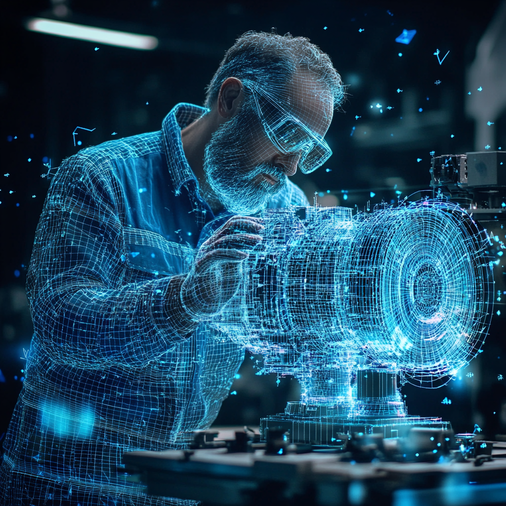
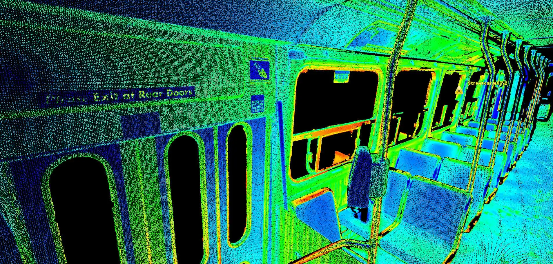
Point cloud to 3D modeling services involve taking a file created with a 3D scanner and turning it into a functional 3D CAD model. When you use a 3D scanner, the scanner takes millions of positional points in 3D space and converts them into a dense cloud. However, the file is simply a collection of points that you can’t do anything with.

Our team takes this otherwise useless point cloud and converts it into a 3D CAD file that you can move around, change, put into an existing assembly, and much more. In the model, there are very few differences between the file and a file you made in SolidWorks from scratch.

With our help, you can get more out of each 3D-scanned part. We optimize the point cloud and go through quality checks to ensure everything is perfect.

You can start with a point cloud from:

  • Faro point cloud files FLS and Scene
  • Leica’s Cyclone / Cloudworx native IMP / PCS files
  • Artec SPROJ files
  • Creaform CSF from GoScan
  • Or even an STL or OBJ file from Shinning 3D

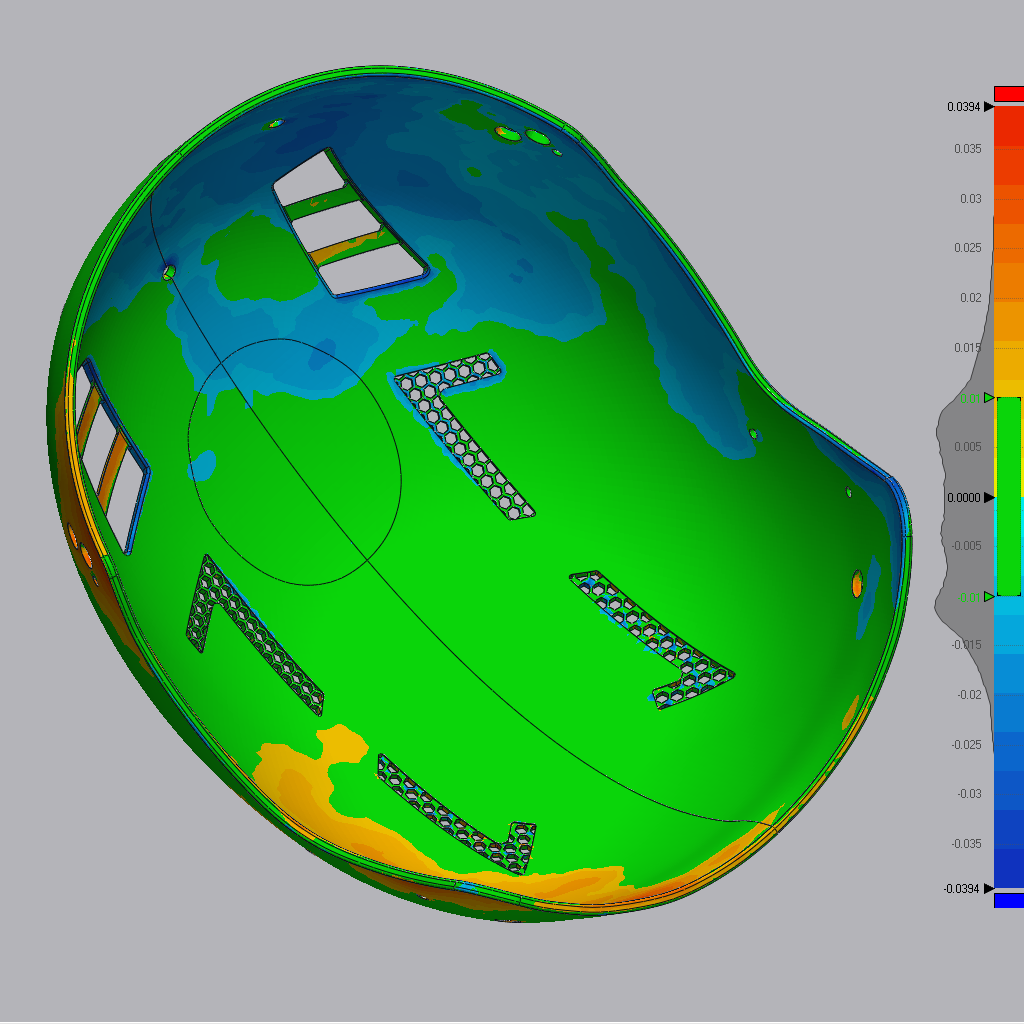
We’ll take that file and convert it into a CAD file of your choosing with up to .005” accuracy.
Why Point Cloud to 3D Models Services Matters

In our experience, it takes twice as long to convert a point cloud than it does to 3D scan the part in the first place. That means a scan that takes an hour to do can easily take 5 hours to convert into a 3D CAD model.

A lot of this time is taken by accuracy checks, quality assurance, and the computing power required to translate those points into a solid model. Without really high-tech computers and an experienced staff, a 5-hour project can become a 50-hour project. That’s why it’s so important that you choose the right team, like our crew at CAD/CAM Services.

A low-quality shop will waste a ton of your time, and they’ll overcharge you for the work. At CAD/CAM Services, we work efficiently to ensure you get the final results as soon as possible, and our services are always affordable and have transparent pricing.
Why Point Cloud to 3D Models Services Matters
Benefits of Point Cloud to 3D Models Services from CAD/CAM Services

Benefits of Point Cloud to 3D Models Services from CAD/CAM Services

When you choose CAD/CAM Services for your next point cloud to 3D model conversion, you’ll appreciate a number of benefits:
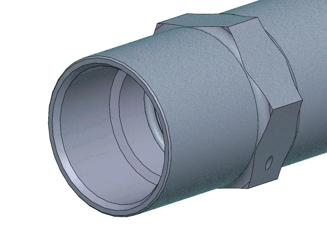
  • More functionality with each scan. We go the extra mile to add more functionality into each scan, allowing you to make changes and updates to your CAD files in the future.
  • Faster turnarounds. With over 100 engineers, expensive 3D scanners, and a ton of computing power, we can commit to really tight deadlines.
  • CAD Perfect® Conversions. Our point cloud to 3D model conversions go through quality checks to ensure the conversion is perfect, every time.
  • Expedited reverse engineering. Shorten your reverse engineering efforts tenfold when you choose CAD/CAM Services for our point cloud to 3D CAD generation services.
  • Highly accurate parts. With accuracies as low as 0.005”, we can meet tight tolerances on each of your parts to guarantee the CAD file is a digital twin.
No items found.

REQUEST A QUOTE

What Goes into Point Cloud to 3D Models Services from CAD/CAM Services?

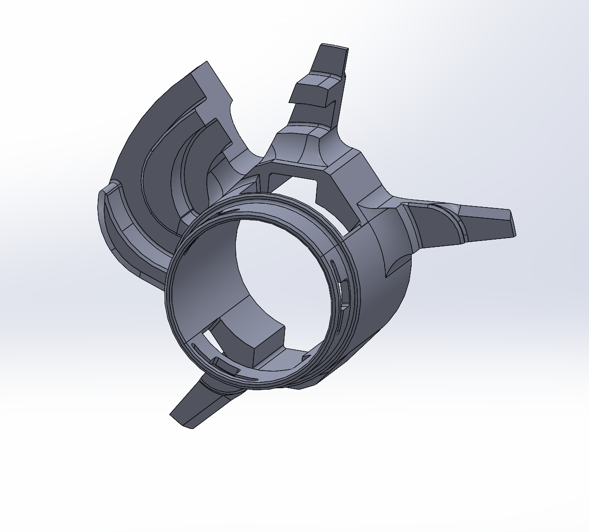
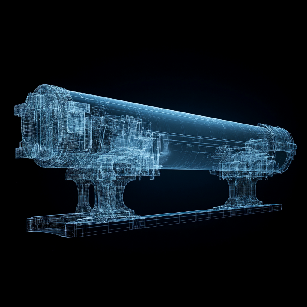
The process of taking a point cloud to a 3D model largely revolves around how much work you’ve already done. We don’t want to waste any of your efforts, so we’ll always pick up wherever you left the project. Whether you have a generated point cloud, a half-converted file, or you don’t even have a 3D scanner, we’ll continue the process until you’re left with a 3D CAD model.

Simply give us all the information you have and whatever files you’ve created, and we’ll do the rest. Let us know which CAD program you’d like to use, and we’ll ensure the final 3D CAD model is compatible with your CAD software of choice.

All of our 3D model generations go through a series of peer reviews and quality checks. This is one way we can guarantee CAD Perfect® results, which is something you can only get from CAD/CAM Services.

Our team is here to make everything as easy as possible. You’ll be left with functional 3D CAD models that you can use however you’d like. If you spot any issues, simply let us know and we’ll correct them in as little as 24 hours.
What Goes into Point Cloud to 3D Models Services from CAD/CAM Services?
Our Point Cloud to 3D Models Services Include:

Our Point Cloud to 3D Models Services Include:

  • 3D CAD Modeling
  • Reverse Engineering
  • 3D Scanning and Digitization
  • Digital Twin Modeling
  • Point Cloud to 3D CAD Generation
  • Point Cloud Conversion
  • 3D Scanning for CNC Machining
  • And Much More (Including Custom Services)
REQUEST A QUOTE

Get a Quote Today

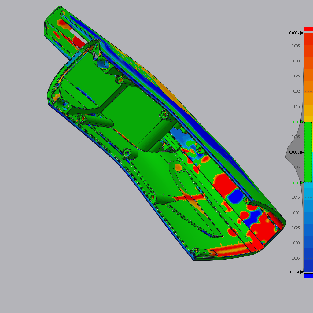
Our team is here to save you time and money, while avoiding the common headaches associated with converting point clouds to 3D CAD models. By trusting us, you’re signing up to receive the best possible results for every project. That’s why so many Fortune 500 companies keep choosing CAD/CAM Services. Choose from our dozens of services, only at CAD/CAM Services.
REQUEST A QUOTE
Get a Quote Today

No items found.

Case Studies

FAQ’s

3D Scanning FAQs
How much does scanning services cost?

It depends on the complexity of the scanned model and material properties. As, for example, it may be much more complicated to properly scan an object with a reflective surface, than a non-reflective surface. It also depends on three main factors:

  1. the physical size of your part
  2. the required scanning resolution
  3. if industrial CT or metallurgy scanning is needed

Simple quick cell phone photos are worth a thousand words to us. To know for sure you can request a quote. It is of course, free – and treated as if an NDA is already in place.

Some averages:

  • The typical 3D scan is somewhere around $200-400 per part.
  • Tomographic (CT) scanning is $600-900 per part.

Because so much of our business is Aerospace related, our scanning – and the completed CAD file HAS to be within ±.005” anywhere on that part, we never use consumer-grade scanners. The scanners we use start at $25,000 and go up to $700,000 (CT) per scanner.

At any given time, we have in excess of $ 5 million just in scanning hardware we use. In addition, a hidden factor of scanning on any system is the assembly and clean up of any scan. The rule of thumb is a 2-1 ratio. So even with our experienced scanning staff, if we spend one-hour scanning; we will then spend an additional two hours of clean up and assembly before our CAD group gets the Point Cloud file to simulate or reverse engineer.

What is the Point Cloud/Mesh/3D Scan?

A point cloud is thousands if not millions of data points located in space by X, Y, Z coordinates. Images of this nature are often captured with Faro Focus or Artec scanners that specialize in large-area scanning.  Most likely you obtain building and territory plans in this file format.

A polygon mesh is a set of triangles located in the same manner. These scans are obtained with Artec, Creaform, Enscan and other handheld scanners. Parts and reverse engineering device scans are usually polygon meshes.

What types of scanners do you use?
  • Faro Arm – Very good for most parts, fast and accurate
  • Turntable scanners – high accuracy, high detail, fast scanning. Great for smaller parts.
  • Portable handheld – may be favorable for some larger parts – if not a tripod-mounted scanner.
  • Long Range – these mount on a tripod, and are intended to scan buildings, plants, and other larger sized projects.
  • Industrial CT scanners – incredibly expensive, but they offer two main benefits – the ability to inside an object (think of a void in a solid object), and their accuracy.  At this level, we are often in the ±.001” – ±.002” range, and often used in metrology scanning.

Which scanner models do you use?
How accurate is 3D scanning?

The scanners we use are as accurate as the industry offers – from anybody at any cost. We use Faro and Artec 3D scanners, in addition to Faro CMM type arms, including the Surveyor tables. Depending on what scanner we use:

  • CT scanners – 4 to 400µm/voxel resolution
  • Artec Portable scanners high accuracy (0.03 – 0.05mm)
  • Artec Portable scanners high resolution (up to 0.15mm)
  • Our CyberGage 360 – generates highly precise full 360 degrees automated scan with accuracy NIST traceable to approximately 7 microns
  • The CyberGage 360 has a system repeatability of ±.005mm.
Do you support CT scanning?

Yes with both the DeskTom and EasyTom CT scanners.  They both support metrology grade Computed Tomography (CT) inspection.  This provides nondestructive, 3D Scanning of Internal and External Geometries.  We use the Volume Graphics VGStudio Max high-end industrial CT software for the demanding of CT applications.

Can your scanners find voids in materials?

Yes. This is one of CT scanners’ major points – to see into objects. This is the best solution for nondestructive quality control.

How good are your 3D CT scanners?
  • 4 to 400µm/voxel resolution
  • Full inspection of large size samples
  • Modular and micro-resolution capability
  • 6 motion axis

What is the minimum price for your scanning services?

For 3D scanning services our minimum order fee is $120.

Can you scan the internals of my parts?

Depending on the situation we can offer you dissecting your part for scanning purposes or use CT if applicable.

Digitizing FAQs
What is the average raster to vector (R2V) 2-D conversion price?

The typical AEC D & E size sheet is $225. There are possible discounts depending on the job size. The more you convert the less you pay.  The bulk of the files we produce are for AutoCAD.

Creating models and drawings over scanned analog documents seem so easy – why such a low price?

In order to make an accurate representation, you have to calibrate the original drawing, which may have deformed during its storage period. Non-dimensioned mediums need to be thoroughly calibrated before digitizing.

Parts of scanned data may be lost due to time and other factors. Because it is important to recreate the design intent,  we need to recreate lost data.

You ONLY receive  Cad Perfect™ files – as if you had drawn these by hand.

Do you support BIM modeling?

Using Revit, yes we do.  Think of BIM as an intelligent 3D model of your building.  We know exactly where all of the HVAC is, IT cabling, electrical, the cost of doors and windows, when mechanical systems need to be serviced, all the way to a room number with a phone number and IP in that room. In addition to our Ray Tracing technology to support some very life-like photo renderings.


What is DHS – Critical Infrastructure Products

The Department of Homeland Security protocol  PPD-21 requirement has deemed that sixteen (16) industries and services are critical to our US Nations security.

These industries  require additional security protocols when creating CAD files. CAD / CAM Services follows all of these requirements. Think of industries and info structures such as power, water, along with fourteen (14) other industries.  For a full list please see Critical Infrastructure Products.

What is a “Calibrated” Mylar image?

Mylar films can be stored in climate-controlled facilities. However, films get skewed and change sizes over time – ironically not linear. So what changes on one end, does not apply to what is in the middle, or the other end.  We have seen ‘J’ size Aerospace Mylars (about 48×180”), vary by a full inch.

CAD/CAM Services utilizes a proprietary process to make Mylar raster images dead on a 5” or 10” grid. Our process was developed in conjunction with, and approved by Boeing engineers.

How can I get a valid CAD model from my old Mylar?

Yes.  We have accurately converted old Mylars into 2D and 3D CAD files for 20 years.

We start with a very good raster scan, generally on Contex 54” or the new 60” scanners.  In addition, we can often work with existing scans that you might have.

After that, we have to adjust the raster image to fit independently in each 5” or10” grid.  Each of the four corners of each grid has to be independently moved and calibrated.This is a tricky, manual, and a proprietary process. But at this point, that Mylar image is back to the original spec. This is exactly what we did for the Air Force.  Over 70,000 J-size Mylars were scanned and calibrated. Now our corrected and calibrated images are the Air Force standard – not the Mylars.

When you import it to your CAD software we make sure that the image is appropriately scaled, calibrated, and truly horizontal and vertical.

What is the accuracy of your digitizing process?

We are proud to announce that we create digitized copies of old non-dimensioned drawings within the Aerospace ±.005” accuracy requirement.

This is exactly the process we have used on several iterations of the 767-8, 300, and 300F.  We would be required to scan 200-300 J-size Mylars, and with zero reference points, and no dimensions. Our next step was to create via FreeForm designs in Catia the 767 wings. All of which was then certified by Boeing.

Reverse Engineering FAQs
What do you guys need to provide me with accurate pricing?

We need to know whether you need your parts to be scanned by us. Or many times we can work with 3D scans provided by third-party companies.  The quality of the scan is everything in our business. Anyway, we strongly advise you to use us for both the scanning and the CAD conversion aspects.  That way, we can control the quality. Sometimes we receive poor quality scans which make it impossible to create truly Cad Perfect™ models for you.  By all means, send us a couple of even cell phone photos, and the rough size of the object.  Most of the time, this will provide us enough information to provide a real bid.

The price depends on the part complexity, size, as well as the target file parametres. We need to know whether you need full parametric models, and your desired accuracy. If you tell us the purpose of reverse-engineered models, we can often provide you with possible solutions. The target CAD software may change the price as well. This includes sophisticated Workstation add-on products such as Composites, Catia electrical wiring, mold design, and others.

What is reverse engineering?

Reverse engineering is the process of analyzing an existing physical object, product, component, assembly, or system to understand its design, dimensions, materials, and functionality so it can be recreated, modified, documented, or manufactured again.

In the CAD and engineering world, reverse engineering typically involves converting a physical part into accurate 3D CAD models, 2D drawings, and engineering documentation.

We often:  1) Capture Existing Data by 3D scanning, 2) create a Digital model, often called a Point Cloud, 3) build a 3D model, and 4) produce the required engineering documentation.

How accurate is reverse engineering?

Typical Accuracy Ranges

Hand Measurements (Calipers, Micrometers) ±0.001" to ±0.010"

Structured Light Scanning ±0.001" to ±0.005"

Laser Scanning ±0.002" to ±0.010"

Photogrammetry ±0.010" to ±0.100"+

CMM Measurement ±0.0001" to ±0.001"

Hybrid Scan + CMM Validation ±0.0005" to ±0.002"

For aerospace, medical, and precision manufacturing applications, a combination of 3D scanning and CMM inspection is often used to achieve the highest accuracy.

Also, there can be two parts to this answer: 1) The accuracy of the scanner, and then 2) if we are going all the way to an editable feature-rich CAD file.  If we are going all the way to the CAD file, we are within ±.005” of any Point Cloud data.

What is the difference between 3D scanning and reverse engineering?

Many people use the terms 3D scanning and reverse engineering interchangeably, but they are not the same thing.

3D scanning is the process of capturing an object's geometry. Reverse engineering is the process of converting that captured data into usable engineering information, such as CAD models, drawings, and manufacturing documentation.

Simple Explanation

Think of it this way:

  • 3D Scanning = Data Collection = a picture of 1,000,000 dots in 3D space
  • Reverse Engineering = Engineering Reconstruction = a feature rich, editable CAD Perfect® CAD file.

A 3D scanner captures the shape of an object. Reverse engineering transforms that shape into an intelligent, editable CAD model that engineers and manufacturers can use.

Can you reverse engineer obsolete parts?

Yes. Reverse engineering obsolete parts is one of the most common reasons organizations pursue reverse engineering services.

When original manufacturers no longer support a component—or when CAD files, drawings, tooling, and engineering records have been lost—reverse engineering can recreate the engineering data needed to manufacture replacement parts and extend the life of critical equipment.

Why Obsolete Parts Need Reverse Engineering

Organizations often face situations where:

  • The original manufacturer is no longer in business.
  • Replacement parts are unavailable.
  • CAD files and drawings have been lost.
  • Legacy equipment remains operational and critical.
  • Lead times for replacement equipment are too long.
  • Modern equivalents are incompatible with existing systems.

Rather than replacing an entire machine, reverse engineering allows companies to reproduce the specific component that has become unavailable.

Can you reverse engineer a part without drawings?

Yes. In fact, most reverse engineering projects begin with no drawings, CAD files, or engineering documentation at all.

Engineers can reverse engineer a part using the physical component itself, measurements, 3D scanning, inspection equipment, and engineering analysis to recreate the original design.

How much does reverse engineering cost?

Typical Reverse Engineering Cost Ranges

Simple Part $500–$2,500

Mechanical Assembly $2,000–$15,000

Tool & Die Reverse Engineering $5,000–$50,000+

Point Cloud to CAD $1,000–$100,000+

Aircraft & Defense Projects Custom Quote

Factors That Influence Cost

Part Complexity

A simple machined block with a few holes may require only a few hours of engineering effort, while a complex casting with freeform surfaces can require significantly more modeling time.

Part Size

Larger parts generally require:

  • More scanning time
  • More measurement data
  • More CAD reconstruction effort
Can reverse engineering create a Digital Twin?

Yes. Reverse engineering is often the first step in creating a Digital Twin, especially when original CAD models, engineering drawings, or product data are unavailable.

A Digital Twin is a digital representation of a physical asset that accurately reflects its geometry, structure, and, in many cases, its operational behavior. Reverse engineering provides the engineering data needed to build that digital representation.

How Reverse Engineering Supports Digital Twin Creation

When an organization has a legacy asset with limited or missing documentation, engineers can:

  1. Capture the physical asset using 3D scanning and measurement technologies.
  2. Create accurate CAD models through reverse engineering.
  3. Generate engineering documentation and metadata.
  4. Integrate the resulting models into simulation, PLM, BIM, IoT, or asset management systems.
  5. Establish a Digital Twin that can be updated throughout the asset's lifecycle.
Can you create manufacturing drawings from a scanned part?

Yes. Manufacturing drawings can be created from a scanned part, but the process involves more than simply scanning the component.

A 3D scan captures the physical geometry of the part, while engineers use reverse engineering techniques to create an accurate CAD model and generate production-ready manufacturing drawings.

The final drawing package may include:

  • Orthographic views
  • Dimensions
  • Tolerances
  • GD&T
  • Material specifications
  • Surface finish requirements
  • Notes and callouts
  • Bill of Materials (BOM)
Do you support aerospace and defense reverse engineering?

Yes. Aerospace and defense reverse engineering is a specialized engineering service used to recreate, modernize, and support legacy aircraft, military systems, ground support equipment, tooling, and mission-critical components when original engineering data is unavailable or obsolete.

Organizations throughout the aerospace and defense industries use reverse engineering to maintain operational readiness, extend service life, and create modern digital engineering assets for aging platforms.

Why Choose CAD/CAM Services?
  • Reverse engineering specialists since 1988
  • Millions of CAD models completed
  • 100+ engineers and drafters
  • CATIA, NX, Creo, SolidWorks, and Inventor experts
  • Aerospace, defense, industrial, and government experience
  • U.S.-based engineering team
  • ITAR-capable projects
  • Model-Based Definition (MBD) expertise
  • Digital Twin and engineering modernization support
Digital Mockup (DMU) FAQs
Can you make me a cool part catalog?

You bet we can. We created millions of files for Amazon’s online catalog, so no doubt we can help you.  Click Link 1, Link 2 or Link 3 for some live Amazon examples. Simply select any file type from the list under the photo.

We directly support TraceParts.com, PartSolutions, GrabCAD, and several others.

What can you do to make a cool part catalog?

There are no limits to creative tasks. Contact us and we will work something out.  This includes part animation, expanded views, opening up assemblies, and full digital mock-ups.

Do you create scenarios for a video demonstration?

We can stage what you want, or propose to you with our exclusive cinematic masterpiece.

General CAD Questions
How do I send a sample, in order to get a quote?

Fill out our quote form, attach your files, or simply send us an email. Tell everything about your project, like the model purpose.

For smaller files < 15 MB you can simply email them to us.  For something larger, just drop them in any number of drop boxes like Dropbox, Google Drive, Microsoft OneDrive and others.  Or if you would like, just contact us for a private, hardened link.

It is fine to use most any time of compression such as  *.zip, *.rar, *.tar, *.7z, *.arc, *.LBR, and even *.iso images.

A direct email is sales@cadcam.org

We also use a hardened OwnCloud web file sharing platform for unlimited file transfers. We provide unique and very private Web Storage Portals, this also supports file syncing for extreme convenience for you. Because so much of our work is DOD or weapons design work, Security – and confidentiality is very important to us.

Will CAD / CAM Services Sign a Non-Disclosure Agreement (NDA)?

Yes. NDAs are a common part of our business. All data is yours – not ours, and treated as proprietary data and not for public consumption or use. Probably 70% of our work is under NDA agreements. We can generally get these signed within the day.

What is the estimated delivery time?

It depends on the scope of work:

  • 2D drawings – small quantity, normally 48 hours.  We have several customers where they contract to us, keeping 4-8 drafters busy full time.
  • 3D models – complexity dependent, but smaller jobs in 2-3 days. Some models we have spent months on.  Again, we have several customers where they contract to us, keeping 6-10 3D CAD designers busy full time.

Simple jobs have a lead time of 48 hours. Larger projects are delivered and invoiced weekly.

Did you really own the trademark Cad Perfect™, Cad Perfect CAD Conversions™ and Cad / Cam Services™?

Yes, we did back in 2008. We started using Cad Perfect™ back in the early 1990s because all of our customers wanted only real Cad Perfect™ work. Back then the buzz words were terms like machine ready, or DXF Traceover and others.

The problem is, nobody wanted that. They all wanted drawings and models that they did not have to touch. Everybody wanted drawings just as if they hand redrew the work themselves.

Thus, Cad / Cam Services™ was the first company to start offering ONLY Cad Perfect™ work.

Do you support the PPD-21 Directive?

Yes we do, and have now for several years. In addition, we also support the industry specific plans as well.

What is the PPD-21 Protocall?

The Presidential Policy Directive 21 (PPD-21) is a Critical Infrastructure Protection and Resilience United States directive that aims to strengthen and secure the country’s critical infrastructure.The goal of this directive is to reduce vulnerabilities, identify and disrupt threats, minimize consequences and hasten response and recovery efforts related to critical infrastructure.

The directive defines resilience as the ability to prepare for and adapt to ever changing conditions, terrorists, and withstand and recover rapidly from disruptions. Resilience includes the ability to withstand and recover from deliberate attacks, accidents, or naturally occurring threats or incidents.

Who is affected by the PPD-21 directive?

The Department of Homeland Security has identified 16 different infostructures:

  1. Chemical Sector,
  2. Commercial Facilities Sector,
  3. Communications Sector,
  4. Critical Manufacturing Sector,
  5. Dams Sector,
  6. Defense Industrial Base Sector,
  7. Emergency Services Sector,
  8. Energy Sector,
  9. Financial Services Sector,
  10. Food and Agriculture Sector,
  11. Government Facilities Sector,
  12. Healthcare and Public Health Sector,
  13. Information Technology Sector,
  14. Nuclear Reactors Materials and Waste Sector,
  15. Transportation Systems Sector,
  16. Water and Wastewater Systems Sector.

This is both Government and private sectors.

If you are in any of these industries, this directive is important to you for many reasons.  Do you know where your critical sections are? Are they well protected? Are there concerns for Hazmat, security clearance requirements, and other concerns?  Can you quickly rebuild what might be lost?

The important part of this means that critical infrastructure must be secure and able to withstand and rapidly recover from all hazards. Achieving this will require integration with the national preparedness system across prevention, protection, mitigation, response, and recovery.

Further details can be found at:  Government PPD-21

DHS – The National Infrastructure Protection Plan details:  The National Infrastructure Protection Plan

Industry specific plans:  2015 Industry specific PPD-21 plans

CAD / CAM Services provides PPD-21 for the following industries:  DHS – CAD / CAM Services

I need my project done today or tomorrow. Can you process rush jobs?

Depending upon when you catch us, yes, we can handle rush jobs. We often work over the holidays, Thanksgiving and even Christmas holidays. If you have a deadline – call us.

For years we have run three shifts of about 30 drafting folks per shift – allowing us to deliver work 3x faster, and seven days a week. Yes, we work 24/7, so you do not have to. The fun never stops here.

For 3D scanning, this is a different question. Because of the common setup work required, at best expect a 48-72 hour turn to be scanned. CAD or simulation services are in addition to that.

By clicking “Accept All Cookies”, you agree to the storing of cookies on your device to enhance site navigation, analyze site usage, and assist in our marketing efforts. View our Privacy Policy for more information.

Point Cloud to 3D Models

Professional Outsourced Point Cloud to 3D Models Services

3D scanning is a great way to expedite every reverse engineering project, but it comes with a big hurdle: how are you supposed to convert your point cloud to a functional 3D CAD model? Our team at CAD/CAM Services is to help with our comprehensive point cloud to 3D model conversion services.

Our team can handle the entire reverse engineering workflow for you, or we can pick up where you left it. Whether you need a 3D scan from scratch, or you just need help taking your point cloud to a final file, we’re here to help.

With a high-quality point cloud, you can quickly have CAD files that you can adjust in no time. Allow our engineers to speed up the full process for you.

REQUEST A QUOTE
What Are Point Cloud to 3D Models Services?

What Are Point Cloud to 3D Models Services?

Point cloud to 3D modeling services involve taking a file created with a 3D scanner and turning it into a functional 3D CAD model. When you use a 3D scanner, the scanner takes millions of positional points in 3D space and converts them into a dense cloud. However, the file is simply a collection of points that you can’t do anything with.

Our team takes this otherwise useless point cloud and converts it into a 3D CAD file that you can move around, change, put into an existing assembly, and much more. In the model, there are very few differences between the file and a file you made in SolidWorks from scratch.

With our help, you can get more out of each 3D-scanned part. We optimize the point cloud and go through quality checks to ensure everything is perfect.

You can start with a point cloud from:

  • Faro point cloud files FLS and Scene
  • Leica’s Cyclone / Cloudworx native IMP / PCS files
  • Artec SPROJ files
  • Creaform CSF from GoScan
  • Or even an STL or OBJ file from Shinning 3D

We’ll take that file and convert it into a CAD file of your choosing with up to .005” accuracy.

Why Point Cloud to 3D Models Services Matters

In our experience, it takes twice as long to convert a point cloud than it does to 3D scan the part in the first place. That means a scan that takes an hour to do can easily take 5 hours to convert into a 3D CAD model.

A lot of this time is taken by accuracy checks, quality assurance, and the computing power required to translate those points into a solid model. Without really high-tech computers and an experienced staff, a 5-hour project can become a 50-hour project. That’s why it’s so important that you choose the right team, like our crew at CAD/CAM Services.

A low-quality shop will waste a ton of your time, and they’ll overcharge you for the work. At CAD/CAM Services, we work efficiently to ensure you get the final results as soon as possible, and our services are always affordable and have transparent pricing.

Why Point Cloud to 3D Models Services Matters
Benefits of Point Cloud to 3D Models Services from CAD/CAM Services

Benefits of Point Cloud to 3D Models Services from CAD/CAM Services

When you choose CAD/CAM Services for your next point cloud to 3D model conversion, you’ll appreciate a number of benefits:

  • More functionality with each scan. We go the extra mile to add more functionality into each scan, allowing you to make changes and updates to your CAD files in the future.
  • Faster turnarounds. With over 100 engineers, expensive 3D scanners, and a ton of computing power, we can commit to really tight deadlines.
  • CAD Perfect® Conversions. Our point cloud to 3D model conversions go through quality checks to ensure the conversion is perfect, every time.
  • Expedited reverse engineering. Shorten your reverse engineering efforts tenfold when you choose CAD/CAM Services for our point cloud to 3D CAD generation services.
  • Highly accurate parts. With accuracies as low as 0.005”, we can meet tight tolerances on each of your parts to guarantee the CAD file is a digital twin.
No items found.

REQUEST A QUOTE

What Goes into Point Cloud to 3D Models Services from CAD/CAM Services?

The process of taking a point cloud to a 3D model largely revolves around how much work you’ve already done. We don’t want to waste any of your efforts, so we’ll always pick up wherever you left the project. Whether you have a generated point cloud, a half-converted file, or you don’t even have a 3D scanner, we’ll continue the process until you’re left with a 3D CAD model.

Simply give us all the information you have and whatever files you’ve created, and we’ll do the rest. Let us know which CAD program you’d like to use, and we’ll ensure the final 3D CAD model is compatible with your CAD software of choice.

All of our 3D model generations go through a series of peer reviews and quality checks. This is one way we can guarantee CAD Perfect® results, which is something you can only get from CAD/CAM Services.

Our team is here to make everything as easy as possible. You’ll be left with functional 3D CAD models that you can use however you’d like. If you spot any issues, simply let us know and we’ll correct them in as little as 24 hours.

What Goes into Point Cloud to 3D Models Services from CAD/CAM Services?
Our Point Cloud to 3D Models Services Include:

Our Point Cloud to 3D Models Services Include:

  • 3D CAD Modeling
  • Reverse Engineering
  • 3D Scanning and Digitization
  • Digital Twin Modeling
  • Point Cloud to 3D CAD Generation
  • Point Cloud Conversion
  • 3D Scanning for CNC Machining
  • And Much More (Including Custom Services)
REQUEST A QUOTE

Get a Quote Today

Our team is here to save you time and money, while avoiding the common headaches associated with converting point clouds to 3D CAD models. By trusting us, you’re signing up to receive the best possible results for every project. That’s why so many Fortune 500 companies keep choosing CAD/CAM Services. Choose from our dozens of services, only at CAD/CAM Services.

REQUEST A QUOTE
Get a Quote Today

FAQ’s

3D Scanning FAQs
How much does scanning services cost?

It depends on the complexity of the scanned model and material properties. As, for example, it may be much more complicated to properly scan an object with a reflective surface, than a non-reflective surface. It also depends on three main factors:

  1. the physical size of your part
  2. the required scanning resolution
  3. if industrial CT or metallurgy scanning is needed

Simple quick cell phone photos are worth a thousand words to us. To know for sure you can request a quote. It is of course, free – and treated as if an NDA is already in place.

Some averages:

  • The typical 3D scan is somewhere around $200-400 per part.
  • Tomographic (CT) scanning is $600-900 per part.

Because so much of our business is Aerospace related, our scanning – and the completed CAD file HAS to be within ±.005” anywhere on that part, we never use consumer-grade scanners. The scanners we use start at $25,000 and go up to $700,000 (CT) per scanner.

At any given time, we have in excess of $ 5 million just in scanning hardware we use. In addition, a hidden factor of scanning on any system is the assembly and clean up of any scan. The rule of thumb is a 2-1 ratio. So even with our experienced scanning staff, if we spend one-hour scanning; we will then spend an additional two hours of clean up and assembly before our CAD group gets the Point Cloud file to simulate or reverse engineer.

What is the Point Cloud/Mesh/3D Scan?

A point cloud is thousands if not millions of data points located in space by X, Y, Z coordinates. Images of this nature are often captured with Faro Focus or Artec scanners that specialize in large-area scanning.  Most likely you obtain building and territory plans in this file format.

A polygon mesh is a set of triangles located in the same manner. These scans are obtained with Artec, Creaform, Enscan and other handheld scanners. Parts and reverse engineering device scans are usually polygon meshes.

What types of scanners do you use?
  • Faro Arm – Very good for most parts, fast and accurate
  • Turntable scanners – high accuracy, high detail, fast scanning. Great for smaller parts.
  • Portable handheld – may be favorable for some larger parts – if not a tripod-mounted scanner.
  • Long Range – these mount on a tripod, and are intended to scan buildings, plants, and other larger sized projects.
  • Industrial CT scanners – incredibly expensive, but they offer two main benefits – the ability to inside an object (think of a void in a solid object), and their accuracy.  At this level, we are often in the ±.001” – ±.002” range, and often used in metrology scanning.

Which scanner models do you use?
How accurate is 3D scanning?

The scanners we use are as accurate as the industry offers – from anybody at any cost. We use Faro and Artec 3D scanners, in addition to Faro CMM type arms, including the Surveyor tables. Depending on what scanner we use:

  • CT scanners – 4 to 400µm/voxel resolution
  • Artec Portable scanners high accuracy (0.03 – 0.05mm)
  • Artec Portable scanners high resolution (up to 0.15mm)
  • Our CyberGage 360 – generates highly precise full 360 degrees automated scan with accuracy NIST traceable to approximately 7 microns
  • The CyberGage 360 has a system repeatability of ±.005mm.
Do you support CT scanning?

Yes with both the DeskTom and EasyTom CT scanners.  They both support metrology grade Computed Tomography (CT) inspection.  This provides nondestructive, 3D Scanning of Internal and External Geometries.  We use the Volume Graphics VGStudio Max high-end industrial CT software for the demanding of CT applications.

Can your scanners find voids in materials?

Yes. This is one of CT scanners’ major points – to see into objects. This is the best solution for nondestructive quality control.

How good are your 3D CT scanners?
  • 4 to 400µm/voxel resolution
  • Full inspection of large size samples
  • Modular and micro-resolution capability
  • 6 motion axis

What is the minimum price for your scanning services?

For 3D scanning services our minimum order fee is $120.

Can you scan the internals of my parts?

Depending on the situation we can offer you dissecting your part for scanning purposes or use CT if applicable.

Digitizing FAQs
What is the average raster to vector (R2V) 2-D conversion price?

The typical AEC D & E size sheet is $225. There are possible discounts depending on the job size. The more you convert the less you pay.  The bulk of the files we produce are for AutoCAD.

Creating models and drawings over scanned analog documents seem so easy – why such a low price?

In order to make an accurate representation, you have to calibrate the original drawing, which may have deformed during its storage period. Non-dimensioned mediums need to be thoroughly calibrated before digitizing.

Parts of scanned data may be lost due to time and other factors. Because it is important to recreate the design intent,  we need to recreate lost data.

You ONLY receive  Cad Perfect™ files – as if you had drawn these by hand.

Do you support BIM modeling?

Using Revit, yes we do.  Think of BIM as an intelligent 3D model of your building.  We know exactly where all of the HVAC is, IT cabling, electrical, the cost of doors and windows, when mechanical systems need to be serviced, all the way to a room number with a phone number and IP in that room. In addition to our Ray Tracing technology to support some very life-like photo renderings.


What is DHS – Critical Infrastructure Products

The Department of Homeland Security protocol  PPD-21 requirement has deemed that sixteen (16) industries and services are critical to our US Nations security.

These industries  require additional security protocols when creating CAD files. CAD / CAM Services follows all of these requirements. Think of industries and info structures such as power, water, along with fourteen (14) other industries.  For a full list please see Critical Infrastructure Products.

What is a “Calibrated” Mylar image?

Mylar films can be stored in climate-controlled facilities. However, films get skewed and change sizes over time – ironically not linear. So what changes on one end, does not apply to what is in the middle, or the other end.  We have seen ‘J’ size Aerospace Mylars (about 48×180”), vary by a full inch.

CAD/CAM Services utilizes a proprietary process to make Mylar raster images dead on a 5” or 10” grid. Our process was developed in conjunction with, and approved by Boeing engineers.

How can I get a valid CAD model from my old Mylar?

Yes.  We have accurately converted old Mylars into 2D and 3D CAD files for 20 years.

We start with a very good raster scan, generally on Contex 54” or the new 60” scanners.  In addition, we can often work with existing scans that you might have.

After that, we have to adjust the raster image to fit independently in each 5” or10” grid.  Each of the four corners of each grid has to be independently moved and calibrated.This is a tricky, manual, and a proprietary process. But at this point, that Mylar image is back to the original spec. This is exactly what we did for the Air Force.  Over 70,000 J-size Mylars were scanned and calibrated. Now our corrected and calibrated images are the Air Force standard – not the Mylars.

When you import it to your CAD software we make sure that the image is appropriately scaled, calibrated, and truly horizontal and vertical.

What is the accuracy of your digitizing process?

We are proud to announce that we create digitized copies of old non-dimensioned drawings within the Aerospace ±.005” accuracy requirement.

This is exactly the process we have used on several iterations of the 767-8, 300, and 300F.  We would be required to scan 200-300 J-size Mylars, and with zero reference points, and no dimensions. Our next step was to create via FreeForm designs in Catia the 767 wings. All of which was then certified by Boeing.

Reverse Engineering FAQs
What do you guys need to provide me with accurate pricing?

We need to know whether you need your parts to be scanned by us. Or many times we can work with 3D scans provided by third-party companies.  The quality of the scan is everything in our business. Anyway, we strongly advise you to use us for both the scanning and the CAD conversion aspects.  That way, we can control the quality. Sometimes we receive poor quality scans which make it impossible to create truly Cad Perfect™ models for you.  By all means, send us a couple of even cell phone photos, and the rough size of the object.  Most of the time, this will provide us enough information to provide a real bid.

The price depends on the part complexity, size, as well as the target file parametres. We need to know whether you need full parametric models, and your desired accuracy. If you tell us the purpose of reverse-engineered models, we can often provide you with possible solutions. The target CAD software may change the price as well. This includes sophisticated Workstation add-on products such as Composites, Catia electrical wiring, mold design, and others.

What is reverse engineering?

Reverse engineering is the process of analyzing an existing physical object, product, component, assembly, or system to understand its design, dimensions, materials, and functionality so it can be recreated, modified, documented, or manufactured again.

In the CAD and engineering world, reverse engineering typically involves converting a physical part into accurate 3D CAD models, 2D drawings, and engineering documentation.

We often:  1) Capture Existing Data by 3D scanning, 2) create a Digital model, often called a Point Cloud, 3) build a 3D model, and 4) produce the required engineering documentation.

How accurate is reverse engineering?

Typical Accuracy Ranges

Hand Measurements (Calipers, Micrometers) ±0.001" to ±0.010"

Structured Light Scanning ±0.001" to ±0.005"

Laser Scanning ±0.002" to ±0.010"

Photogrammetry ±0.010" to ±0.100"+

CMM Measurement ±0.0001" to ±0.001"

Hybrid Scan + CMM Validation ±0.0005" to ±0.002"

For aerospace, medical, and precision manufacturing applications, a combination of 3D scanning and CMM inspection is often used to achieve the highest accuracy.

Also, there can be two parts to this answer: 1) The accuracy of the scanner, and then 2) if we are going all the way to an editable feature-rich CAD file.  If we are going all the way to the CAD file, we are within ±.005” of any Point Cloud data.

What is the difference between 3D scanning and reverse engineering?

Many people use the terms 3D scanning and reverse engineering interchangeably, but they are not the same thing.

3D scanning is the process of capturing an object's geometry. Reverse engineering is the process of converting that captured data into usable engineering information, such as CAD models, drawings, and manufacturing documentation.

Simple Explanation

Think of it this way:

  • 3D Scanning = Data Collection = a picture of 1,000,000 dots in 3D space
  • Reverse Engineering = Engineering Reconstruction = a feature rich, editable CAD Perfect® CAD file.

A 3D scanner captures the shape of an object. Reverse engineering transforms that shape into an intelligent, editable CAD model that engineers and manufacturers can use.

Can you reverse engineer obsolete parts?

Yes. Reverse engineering obsolete parts is one of the most common reasons organizations pursue reverse engineering services.

When original manufacturers no longer support a component—or when CAD files, drawings, tooling, and engineering records have been lost—reverse engineering can recreate the engineering data needed to manufacture replacement parts and extend the life of critical equipment.

Why Obsolete Parts Need Reverse Engineering

Organizations often face situations where:

  • The original manufacturer is no longer in business.
  • Replacement parts are unavailable.
  • CAD files and drawings have been lost.
  • Legacy equipment remains operational and critical.
  • Lead times for replacement equipment are too long.
  • Modern equivalents are incompatible with existing systems.

Rather than replacing an entire machine, reverse engineering allows companies to reproduce the specific component that has become unavailable.

Can you reverse engineer a part without drawings?

Yes. In fact, most reverse engineering projects begin with no drawings, CAD files, or engineering documentation at all.

Engineers can reverse engineer a part using the physical component itself, measurements, 3D scanning, inspection equipment, and engineering analysis to recreate the original design.

How much does reverse engineering cost?

Typical Reverse Engineering Cost Ranges

Simple Part $500–$2,500

Mechanical Assembly $2,000–$15,000

Tool & Die Reverse Engineering $5,000–$50,000+

Point Cloud to CAD $1,000–$100,000+

Aircraft & Defense Projects Custom Quote

Factors That Influence Cost

Part Complexity

A simple machined block with a few holes may require only a few hours of engineering effort, while a complex casting with freeform surfaces can require significantly more modeling time.

Part Size

Larger parts generally require:

  • More scanning time
  • More measurement data
  • More CAD reconstruction effort
Can reverse engineering create a Digital Twin?

Yes. Reverse engineering is often the first step in creating a Digital Twin, especially when original CAD models, engineering drawings, or product data are unavailable.

A Digital Twin is a digital representation of a physical asset that accurately reflects its geometry, structure, and, in many cases, its operational behavior. Reverse engineering provides the engineering data needed to build that digital representation.

How Reverse Engineering Supports Digital Twin Creation

When an organization has a legacy asset with limited or missing documentation, engineers can:

  1. Capture the physical asset using 3D scanning and measurement technologies.
  2. Create accurate CAD models through reverse engineering.
  3. Generate engineering documentation and metadata.
  4. Integrate the resulting models into simulation, PLM, BIM, IoT, or asset management systems.
  5. Establish a Digital Twin that can be updated throughout the asset's lifecycle.
Can you create manufacturing drawings from a scanned part?

Yes. Manufacturing drawings can be created from a scanned part, but the process involves more than simply scanning the component.

A 3D scan captures the physical geometry of the part, while engineers use reverse engineering techniques to create an accurate CAD model and generate production-ready manufacturing drawings.

The final drawing package may include:

  • Orthographic views
  • Dimensions
  • Tolerances
  • GD&T
  • Material specifications
  • Surface finish requirements
  • Notes and callouts
  • Bill of Materials (BOM)
Do you support aerospace and defense reverse engineering?

Yes. Aerospace and defense reverse engineering is a specialized engineering service used to recreate, modernize, and support legacy aircraft, military systems, ground support equipment, tooling, and mission-critical components when original engineering data is unavailable or obsolete.

Organizations throughout the aerospace and defense industries use reverse engineering to maintain operational readiness, extend service life, and create modern digital engineering assets for aging platforms.

Why Choose CAD/CAM Services?
  • Reverse engineering specialists since 1988
  • Millions of CAD models completed
  • 100+ engineers and drafters
  • CATIA, NX, Creo, SolidWorks, and Inventor experts
  • Aerospace, defense, industrial, and government experience
  • U.S.-based engineering team
  • ITAR-capable projects
  • Model-Based Definition (MBD) expertise
  • Digital Twin and engineering modernization support
Digital Mockup (DMU) FAQs
Can you make me a cool part catalog?

You bet we can. We created millions of files for Amazon’s online catalog, so no doubt we can help you.  Click Link 1, Link 2 or Link 3 for some live Amazon examples. Simply select any file type from the list under the photo.

We directly support TraceParts.com, PartSolutions, GrabCAD, and several others.

What can you do to make a cool part catalog?

There are no limits to creative tasks. Contact us and we will work something out.  This includes part animation, expanded views, opening up assemblies, and full digital mock-ups.

Do you create scenarios for a video demonstration?

We can stage what you want, or propose to you with our exclusive cinematic masterpiece.

General CAD Questions
How do I send a sample, in order to get a quote?

Fill out our quote form, attach your files, or simply send us an email. Tell everything about your project, like the model purpose.

For smaller files < 15 MB you can simply email them to us.  For something larger, just drop them in any number of drop boxes like Dropbox, Google Drive, Microsoft OneDrive and others.  Or if you would like, just contact us for a private, hardened link.

It is fine to use most any time of compression such as  *.zip, *.rar, *.tar, *.7z, *.arc, *.LBR, and even *.iso images.

A direct email is sales@cadcam.org

We also use a hardened OwnCloud web file sharing platform for unlimited file transfers. We provide unique and very private Web Storage Portals, this also supports file syncing for extreme convenience for you. Because so much of our work is DOD or weapons design work, Security – and confidentiality is very important to us.

Will CAD / CAM Services Sign a Non-Disclosure Agreement (NDA)?

Yes. NDAs are a common part of our business. All data is yours – not ours, and treated as proprietary data and not for public consumption or use. Probably 70% of our work is under NDA agreements. We can generally get these signed within the day.

What is the estimated delivery time?

It depends on the scope of work:

  • 2D drawings – small quantity, normally 48 hours.  We have several customers where they contract to us, keeping 4-8 drafters busy full time.
  • 3D models – complexity dependent, but smaller jobs in 2-3 days. Some models we have spent months on.  Again, we have several customers where they contract to us, keeping 6-10 3D CAD designers busy full time.

Simple jobs have a lead time of 48 hours. Larger projects are delivered and invoiced weekly.

Did you really own the trademark Cad Perfect™, Cad Perfect CAD Conversions™ and Cad / Cam Services™?

Yes, we did back in 2008. We started using Cad Perfect™ back in the early 1990s because all of our customers wanted only real Cad Perfect™ work. Back then the buzz words were terms like machine ready, or DXF Traceover and others.

The problem is, nobody wanted that. They all wanted drawings and models that they did not have to touch. Everybody wanted drawings just as if they hand redrew the work themselves.

Thus, Cad / Cam Services™ was the first company to start offering ONLY Cad Perfect™ work.

Do you support the PPD-21 Directive?

Yes we do, and have now for several years. In addition, we also support the industry specific plans as well.

What is the PPD-21 Protocall?

The Presidential Policy Directive 21 (PPD-21) is a Critical Infrastructure Protection and Resilience United States directive that aims to strengthen and secure the country’s critical infrastructure.The goal of this directive is to reduce vulnerabilities, identify and disrupt threats, minimize consequences and hasten response and recovery efforts related to critical infrastructure.

The directive defines resilience as the ability to prepare for and adapt to ever changing conditions, terrorists, and withstand and recover rapidly from disruptions. Resilience includes the ability to withstand and recover from deliberate attacks, accidents, or naturally occurring threats or incidents.

Who is affected by the PPD-21 directive?

The Department of Homeland Security has identified 16 different infostructures:

  1. Chemical Sector,
  2. Commercial Facilities Sector,
  3. Communications Sector,
  4. Critical Manufacturing Sector,
  5. Dams Sector,
  6. Defense Industrial Base Sector,
  7. Emergency Services Sector,
  8. Energy Sector,
  9. Financial Services Sector,
  10. Food and Agriculture Sector,
  11. Government Facilities Sector,
  12. Healthcare and Public Health Sector,
  13. Information Technology Sector,
  14. Nuclear Reactors Materials and Waste Sector,
  15. Transportation Systems Sector,
  16. Water and Wastewater Systems Sector.

This is both Government and private sectors.

If you are in any of these industries, this directive is important to you for many reasons.  Do you know where your critical sections are? Are they well protected? Are there concerns for Hazmat, security clearance requirements, and other concerns?  Can you quickly rebuild what might be lost?

The important part of this means that critical infrastructure must be secure and able to withstand and rapidly recover from all hazards. Achieving this will require integration with the national preparedness system across prevention, protection, mitigation, response, and recovery.

Further details can be found at:  Government PPD-21

DHS – The National Infrastructure Protection Plan details:  The National Infrastructure Protection Plan

Industry specific plans:  2015 Industry specific PPD-21 plans

CAD / CAM Services provides PPD-21 for the following industries:  DHS – CAD / CAM Services

I need my project done today or tomorrow. Can you process rush jobs?

Depending upon when you catch us, yes, we can handle rush jobs. We often work over the holidays, Thanksgiving and even Christmas holidays. If you have a deadline – call us.

For years we have run three shifts of about 30 drafting folks per shift – allowing us to deliver work 3x faster, and seven days a week. Yes, we work 24/7, so you do not have to. The fun never stops here.

For 3D scanning, this is a different question. Because of the common setup work required, at best expect a 48-72 hour turn to be scanned. CAD or simulation services are in addition to that.