By clicking “Accept All Cookies”, you agree to the storing of cookies on your device to enhance site navigation, analyze site usage, and assist in our marketing efforts. View our Privacy Policy for more information.
2D CAD Services

CAD Perfect® Conversion with CAD / CAM Services

CAD Perfect® conversions are a simple way to save time, save engineering efforts, save money, and avoid headaches during your conversion process. Any time we speak to a department that has hand-drawn legacy engineering drawings, we offer our professional-grade CAD Perfect® conversions. 

What makes our conversions CAD Perfect®? They are

  • Dimensionally Accurate
  • Contain Fully Constrained Geometry
  • Made with Clean Feature Tree
  • Optimized for Manufacturing
  • Come with Error-Free Documentation
Request A QUOTE

What Are CAD Perfect® Conversions? 

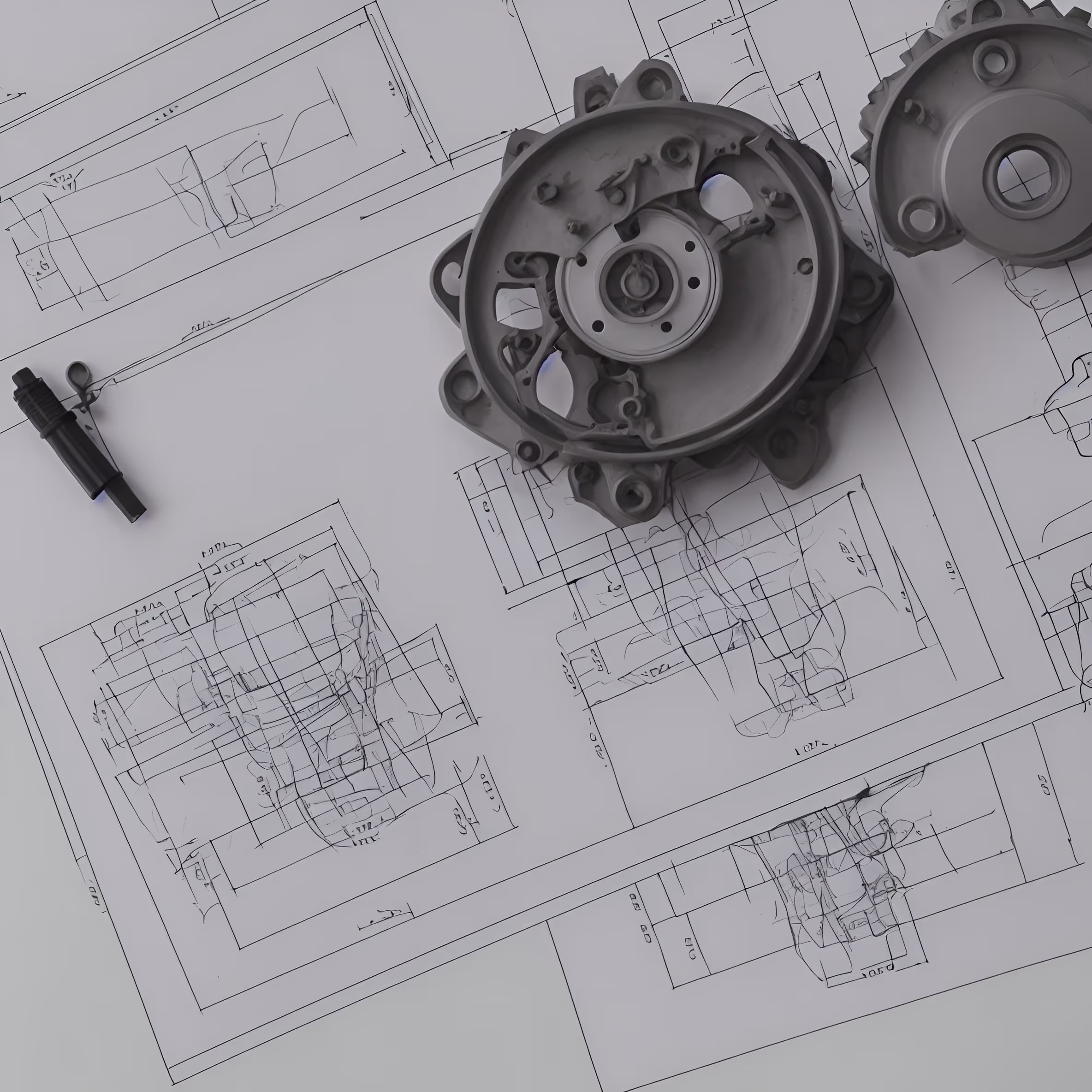
CAD Perfect® conversions are an offering from CAD/CAM Services where we take your original hand-drawn engineering drawings and convert them into digital Computer-Aided Drafting (CAD) files. We actually trademarked the phrase “CAD Perfect®”, because we believe we’re the only outsourced CAD team that can live up to that expectation. 

When you order CAD Perfect® conversions, our team will manually redraw your shared legacy drawing. Luckily, we have a team of nearly 100 engineers and draftsmen who work on staggered shifts to offer 24/7 availability and around-the-clock effort. The result? Faster conversions that meet our “CAD Perfect®” guarantee and an ability to convert a thousand 3D CAD files daily.

A Quick Look at the CAD Perfect® Conversion Process

We make sure the process is super simple for your team, and it all starts with a consultation. This could be a quick phone call or conversation where you outline how many drawings you have, what CAD program you’d like the drawings to be made in, and what sort of timeline you’re working with.

From there, we’ll put together a quick and free quote that further explains how the CAD Perfect® conversion process works. Once the signatures are out of the way, our team will get started.

Our engineering department is massive and filled with highly trained CAD experts. We’ll take a 2D scan of your original hand-drawn engineering drawings and open your CAD program of choice on our computers. We will then meticulously redraw every line, arc, hatch, and detail from your original drawing in 2D or 3D CAD. 

Since we’re drawing with the CAD program you use, the files will be native and simple for your team to use. We have experts that can make your drawings in any of the common CAD software options:

The drawing will then go through an internal peer review where another engineer checks the CAD model against the original scanned document, makes any corrections, and ensures the quality of the final file is CAD Perfect®.

Once everything looks good to us, we’ll send the final CAD files to you through an encrypted, safe document folder — this is the same method that the DoD uses to share government-classified files, and it’s been our go-to method of sharing documents for a while.

What can you expect to receive specifically? CAD documents in your native CAD program that will open up immediately without any problems. It’s also worth mentioning that you fully own the drawings, IP, and technical data in each design, we don’t.

If you find anything you don’t like about the drawing, we will fix it for free within 24 hours and send it back. 

Why CAD Perfect® Conversions Matter

A lot of companies offer CAD conversions, but no one offers CAD Perfect® conversions. The difference comes down to our expert team at CAD/CAM Services. We’ve tried using our competitors in the past to see the difference, and it’s shocking: a lot of other outfits don’t have the same turnaround times, pricing, and quality checks that we have.

That means that choosing the wrong company will waste your time and money, and might result in unusable CAD files. Plus, giving your intellectual property to a shady outsourced CAD team can lead to big trouble.

At CAD/CAM Services, we offer CAD Perfect® conversions that you won’t find elsewhere. We want the final CAD file to be perfect, so we always go the extra distance to make sure that’s the case. With us in your corner, you’ll get high-quality 2D CAD files or 3D CAD models every time.

Benefits of CAD Perfect® Conversions from CAD/CAM Services

A lot of people are confused when it comes to engineering CAD conversions. Why should you convert to a digital file when the Mylar drawing is perfectly fine? Well, what happens if there’s a flood, fire, break-in, or someone just misplaces the drawing? We’ve spoken to hundreds of clients that received CAD Perfect® conversions from us, and they all had similar reasons why they chose to convert their drawings with us:

  • Better security. Digital files are exponentially more secure than storing physical drawings in an unsupervised backroom. With digital copies, you can easily control who can access the drawings and you get a paper trail of who looked at the drawings, and when. As a result, your drawings are more secure.
  • Easier to change the design. Changing a hand drawing takes a lot of experience with manual drafting, and it’s certainly not easy. With a CAD file, you can save a new copy and change the design in less than a minute.
  • Faster drawing sharing. We can all agree that sharing a CAD file is much easier than sharing a physical drawing. After a CAD Perfect® conversion, you can share drawings across departments and with other companies within minutes.
  • Check for design precision. With a hand drawing, complex angles and components might be incorrectly measured, making the part impossible to make. After making it in CAD, you can get precise measurements that will help your manufacturer make the part.
  • Less stress finding the right drawing. The beauty of a professional outsourced CAD conversion is that you can store the files in your server however you’d like. You can organize each drawing by component type, vendor, market, date, or drawing ID. This makes it much easier to find the right drawing, instead of leafing through a pile of Mylar drawings in a drawer.

Get a Quote Today

Our team at CAD/CAM Services is here to help you. We take a lot of pride in our work, and we take our conversion services very seriously — that’s the sole reason why we trademarked “CAD Perfect®” in the first place. We want every CAD file to be perfect, giving you peace of mind.

Reach out today to get a free quote, and allow our expert draftsmen to walk you through the full process and answer any of your questions. After all, the only place to get CAD Perfect® conversions is at CAD/CAM Services. 

Feel free to explore our FAQ section below to get quick answers to commonly asked questions. 

Request A QUOTE

FAQ’s

Cad Conversion FAQs

What does Catia cost with options?

CATIA pricing isn’t publicly fixed and varies a lot by modules, licensing type, region, and whether it’s enterprise-negotiated (which it usually is). But I can give you realistic industry ranges so you understand what “CATIA with options” actually costs.

Baseline: CATIA is Enterprise Software

CATIA is typically sold through Dassault Systèmes resellers with modular licensing.

You don’t buy “one CATIA”—you assemble a configuration like:

  • Mechanical design
  • Surface design
  • Assembly design
  • MBD (Model-Based Definition)
  • Simulation
  • Manufacturing
  • PLM integration

Each “option” is a paid module.

Typical Cost Ranges (Real-World Estimates)

1. Entry-Level CATIA Configuration (rare in aerospace)

  • Basic mechanical + assembly + drafting

👉 ~$5,000 to $10,000 per seat per year

2. Professional Mechanical + Surfacing Setup

  • Advanced part design
  • Surface modeling
  • Large assembly tools

👉 ~$10,000 to $25,000 per seat per year

3. Aerospace / Full Engineering Stack (“with options”)

Includes things like:

  • Advanced surfacing (Class A)
  • MBD / GD&T integration
  • Kinematics
  • Advanced assembly management
  • Manufacturing prep
  • Simulation modules (optional add-ons)

👉 ~$20,000 to $40,000+ per seat per year

4. Full Enterprise / PLM-Connected Stack

When CATIA is bundled with:

  • 3DEXPERIENCE
  • Simulation tools
  • Manufacturing planning
  • Collaboration + cloud platform

👉 $40,000 to $70,000+ per seat per year (sometimes more)

License Type Matters A LOT

Named User (most common now)

  • Per engineer license
  • Annual subscription
  • Highest flexibility

Floating / Network

  • Shared pool of licenses
  • More expensive upfront but efficient for large teams

Enterprise Agreements

  • Custom pricing
  • Includes support, PLM, training, cloud services

What Drives CATIA Cost Up

You pay more for:

  • Advanced surfacing (Aerospace Class A)
  • MBD / PMI capabilities
  • Large assembly performance tools
  • Aerospace industry templates
  • PLM integration (3DEXPERIENCE)
  • Simulation modules
  • Manufacturing (CNC, composites, tooling)

Why It Feels Expensive vs SOLIDWORKS

CATIA is not just CAD—it’s:

  • Engineering platform
  • Digital thread backbone
  • Aerospace-grade design system
  • PLM-integrated environment

So you're paying for:

  • Compliance capability
  • Configuration control
  • Multi-discipline engineering
  • Lifecycle traceability

Practical Reality (Important Insight)

Most companies don’t buy “full CATIA with everything.”

Instead they:

  • Start with a core CAD package
  • Add only needed modules
  • Expand as programs require

Aerospace OEMs like:

  • Airbus
  • Boeing

often have multi-million-dollar annual CATIA + PLM environments spread across thousands of users.

Bottom Line

  • Entry use: ~$5K–$10K/year per seat
  • Serious engineering: $10K–$40K/year per seat
  • Full aerospace digital engineering stack: $40K–$70K+/year per seat

If you’re thinking strategically:

CATIA becomes expensive when you buy capability for the entire digital engineering lifecycle, not just modeling parts.

If you want, I can break down:

  • CATIA vs NX total cost of ownership
  • Or what modules you actually need for CAD services / reverse engineering / MBD work (so you don’t overbuy)

What is better SolidWorks vs. PTC Creo

SOLIDWORKS and PTC Creo are both excellent CAD systems, but they tend to serve different segments of the market.

For many small-to-mid-sized manufacturing companies, SOLIDWORKS is often easier to adopt and staff. For highly complex engineering environments, large assemblies, configuration-heavy products, and aerospace/defense programs, Creo has some significant advantages.

Quick Comparison

CategorySOLIDWORKSCreoEase of learningEasierSteeper learning curveMechanical designExcellentExcellentLarge assembliesGoodVery strongComplex product configurationsGoodExcellentAerospace & defense adoptionModerateStrongMBD capabilitiesStrongVery strongPLM integrationGoodExcellentSimulation integrationGoodStrongEnterprise engineeringGoodExcellent

Why Choose SOLIDWORKS?

Faster Adoption

SOLIDWORKS is often considered more approachable for:

  • Startups
  • Small manufacturers
  • Job shops
  • Product development firms

Benefits include:

  • Large user community
  • Abundant training resources
  • Easier hiring

Strong Mechanical Design

SOLIDWORKS excels at:

  • Parts
  • Assemblies
  • Weldments
  • Sheet metal
  • Fixtures
  • General manufacturing design

Broad Industry Use

You'll find SOLIDWORKS in:

  • Automation
  • Consumer products
  • Medical devices
  • Industrial equipment
  • General manufacturing

Why Choose Creo?

Parametric Modeling Heritage

PTC Creo evolved from Pro/ENGINEER, one of the pioneers of parametric CAD.

Creo is known for:

  • Robust feature management
  • Complex engineering changes
  • Configuration-intensive products

Large Assembly Performance

Creo performs especially well when managing:

  • Aircraft subsystems
  • Defense equipment
  • Heavy machinery
  • Complex industrial systems

Advanced Model-Based Definition

Creo has long been a leader in:

  • Embedded GD&T
  • Digital product definition
  • Model-Based Definition (MBD)

This is important for aerospace and defense digital engineering programs.

PLM and Digital Thread

One of Creo's biggest strengths is its integration with:

  • Windchill

This supports:

  • Configuration management
  • Engineering changes
  • Digital thread initiatives
  • Digital twin development

For organizations managing products over decades, this can be a major advantage.

Aerospace & Defense

Creo has a strong presence in:

  • Defense contractors
  • Aerospace suppliers
  • Government programs
  • Long-lifecycle equipment

Common use cases include:

  • Missile systems
  • Military vehicles
  • Aircraft subsystems
  • Sustainment programs

Its emphasis on configuration management and lifecycle support aligns well with defense requirements.

Reverse Engineering and CAD Remastering

Both tools can handle:

  • Scan-to-CAD
  • Legacy drawing conversion
  • Parametric reconstruction

However, Creo is often favored in environments where the deliverable must support:

  • Long-term sustainment
  • Configuration control
  • PLM integration
  • MBD workflows

Digital Twin Readiness

Modern digital engineering programs often rely on:

CAD

MBD

PLM

Digital Thread

Digital Twin

Creo's integration with Windchill makes it particularly strong in these workflows.

Cost and Talent Considerations

SOLIDWORKS

Advantages:

  • Larger talent pool
  • Easier onboarding
  • Common among manufacturers
  • Widely taught

Creo

Advantages:

  • Strong enterprise engineering capabilities
  • Common in regulated industries
  • Powerful configuration management

Challenges:

  • Smaller talent pool
  • Longer learning curve

For a CAD Services Business

If your customers are:

General Manufacturing

Choose expertise in:

  • SOLIDWORKS
  • Reverse engineering
  • Product development
  • Manufacturing support

Aerospace, Defense, and Long-Life Assets

Choose expertise in:

  • Creo
  • MBD
  • Windchill
  • PLM
  • Digital thread
  • Digital twin development
  • Legacy equipment modernization

Bottom Line

  • SOLIDWORKS is often the best choice for broad commercial manufacturing work, rapid product development, and ease of adoption.
  • Creo is often the stronger choice for complex engineering programs, configuration-controlled products, aerospace and defense environments, and digital engineering initiatives tied to PLM and lifecycle management.

If your long-term goal is to build a high-end aerospace/defense CAD services practice focused on CAD remastering, MBD, PLM integration, digital twins, and sustainment programs, Creo is generally closer to the enterprise engineering workflows used in those environments, while SOLIDWORKS remains extremely valuable for serving a wider manufacturing customer base.

And think of it this way, if my goal is to create a part or a good 3D assembly - SolidWorks. If however you wish a true interactive Parametric Design - PTC Creo. Creo is up there with NX and Catia for handeling complex assemblies. However, SolidWorks is used - and sold 5-1 vs. PTC Creo worldwide.

Why should I use Solidworks vs. AutoCAD

The choice between SOLIDWORKS and AutoCAD is less about which is better and more about what you're trying to accomplish. They were originally designed for different purposes.

The Fundamental Difference

SOLIDWORKS

SOLIDWORKS is a 3D parametric mechanical design system.

It is intended for:

  • Parts
  • Assemblies
  • Mechanical products
  • Manufacturing
  • Engineering analysis

AutoCAD

AutoCAD is primarily a drafting and documentation platform.

It is intended for:

  • 2D drawings
  • Schematics
  • Layouts
  • Floor plans
  • General drafting

Example: Designing a Gearbox

In AutoCAD

You would typically:

  • Draw views manually
  • Create dimensions manually
  • Manage changes manually
  • Update drawings manually

In SOLIDWORKS

You would:

  • Build a 3D assembly
  • Create relationships between components
  • Generate drawings automatically
  • Update all views automatically when designs change

For mechanical products, this can save enormous amounts of time.

Parametric Design

One of the biggest advantages of SOLIDWORKS is parametric modeling.

For example:

If a shaft diameter changes:

25 mm → 30 mm

Associated features can update automatically.

In AutoCAD, many changes must be made manually.

Assemblies

SOLIDWORKS

Designed for:

  • Machines
  • Robots
  • Industrial equipment
  • Consumer products

Capabilities include:

  • Motion studies
  • Interference detection
  • Assembly relationships
  • Exploded views

AutoCAD

Can represent assemblies but lacks the same mechanical design capabilities.

Manufacturing Integration

SOLIDWORKS is built around manufacturing workflows.

Supports:

  • CNC manufacturing
  • CAM integration
  • BOM generation
  • Sheet metal design
  • Weldments
  • Mold design

AutoCAD is primarily a drafting tool and generally requires additional systems for these workflows.

Simulation

SOLIDWORKS supports:

  • Stress analysis
  • Motion analysis
  • Thermal studies
  • Design optimization

AutoCAD is not intended for engineering simulation.

Reverse Engineering

If you're creating CAD models from:

  • Legacy drawings
  • Laser scans
  • Physical parts

SOLIDWORKS is generally much more effective because it produces parametric 3D models that can be modified and reused.

AutoCAD is often used to document the results but not as the primary modeling environment.

Product Lifecycle Management

SOLIDWORKS integrates with:

  • SOLIDWORKS PDM
  • Manufacturing systems
  • ERP systems

This supports:

  • Revision control
  • Engineering change management
  • Configuration control

AutoCAD can participate in these workflows but is not usually the centerpiece of them.

When AutoCAD Is the Better Choice

AutoCAD remains excellent for:

  • Architectural drafting
  • Facility layouts
  • Electrical schematics
  • Piping diagrams
  • Site plans
  • Legacy drawing conversion
  • General technical documentation

Many industries still rely heavily on AutoCAD drawings.

When SOLIDWORKS Is the Better Choice

Choose SOLIDWORKS if you need to:

  • Design manufactured products
  • Build assemblies
  • Create production-ready models
  • Perform engineering analysis
  • Generate BOMs
  • Support manufacturing workflows

Examples:

  • Machinery
  • Automation systems
  • Medical devices
  • Consumer products
  • Industrial equipment

Aerospace & Defense Perspective

For aerospace and defense work:

  • AutoCAD is often used for documentation, facilities, and legacy drawings.
  • SOLIDWORKS is commonly used by suppliers and equipment manufacturers.
  • Large OEM programs frequently use:
    • CATIA
    • Siemens NX
    • PTC Creo

If your goal is to build expertise in CAD services, reverse engineering, CAD remastering, digital twins, and manufacturing support, SOLIDWORKS generally offers far more engineering capability than AutoCAD because it creates intelligent 3D models rather than primarily serving as a drafting environment.

Why should I use Solidworks vs. Autodesk Inventor?

SOLIDWORKS and Autodesk Inventor are both powerful mid-market mechanical CAD systems. Neither is universally "better"—the best choice depends on your customers, workflow, and long-term goals.

Quick Comparison

AreaSOLIDWORKSInventorMarket adoptionVery large user baseStrong Autodesk ecosystemMechanical designExcellentExcellentEase of hiring experienced usersUsually easierGoodThird-party add-onsExtensiveGoodManufacturing suppliersVery commonCommonIntegration with Autodesk productsLimitedExcellentBIM/AEC workflowsLess commonStronger via Autodesk ecosystemCAM integrationStrongStrong

Why Choose SOLIDWORKS?

Large Industry Adoption

SOLIDWORKS is widely used in:

  • Manufacturing
  • Industrial equipment
  • Automation
  • Consumer products
  • Medical devices

Benefits:

  • Large talent pool
  • Extensive training resources
  • Large community support

Strong Design Productivity

SOLIDWORKS is known for:

  • Intuitive interface
  • Fast part modeling
  • Efficient assembly creation
  • Rapid prototyping workflows

Extensive Third-Party Ecosystem

Thousands of suppliers provide:

  • CAD libraries
  • Analysis tools
  • PDM extensions
  • Manufacturing integrations

Why Choose Inventor?

Autodesk Ecosystem

Autodesk Inventor works closely with:

  • AutoCAD
  • Fusion
  • Revit

This can be valuable when projects involve both mechanical and facility/building design.

Legacy AutoCAD Users

Many companies adopted Inventor because they already had substantial AutoCAD investments.

Benefits include:

  • Familiar workflows
  • Easier migration
  • Shared Autodesk data management tools

Equipment and Plant Design

Inventor is often found in:

  • Factory equipment
  • Material handling systems
  • Packaging machinery
  • Process plants

Assemblies

Both handle assemblies well.

Typical strengths:

SOLIDWORKS

  • Fast everyday assembly design
  • Large installed base among manufacturers
  • Strong supplier collaboration

Inventor

  • Good large-assembly performance
  • Strong integration with Autodesk Vault
  • Effective design automation capabilities

Simulation

Both support:

  • Stress analysis
  • Motion studies
  • Basic thermal analysis

For advanced aerospace or defense simulation, organizations often move beyond both platforms and use dedicated tools such as:

  • ANSYS
  • Abaqus

Data Management

SOLIDWORKS

Often paired with:

  • SOLIDWORKS PDM

Inventor

Often paired with:

  • Autodesk Vault

Both provide:

  • Revision control
  • File management
  • Change tracking

Aerospace & Defense Considerations

For serious aerospace OEM work, neither SOLIDWORKS nor Inventor is typically the primary design platform.

Most major aerospace and defense organizations rely heavily on:

  • CATIA
  • Siemens NX
  • PTC Creo

However, SOLIDWORKS and Inventor are frequently used by:

  • Suppliers
  • Tooling companies
  • Fixture designers
  • Equipment manufacturers
  • Small engineering firms

For a CAD Services Business

If you're offering:

  • General mechanical design services
  • Product development
  • Equipment design
  • Manufacturing support

SOLIDWORKS often provides the broadest market reach because of its large user base.

If you're targeting:

  • Autodesk-centric customers
  • AutoCAD-heavy organizations
  • Factory and plant equipment projects

Inventor can be an excellent fit.

Practical Recommendation

If your goal is to build a CAD services business that serves a wide range of manufacturing clients:

  1. Learn SOLIDWORKS first.
  2. Add Inventor if you encounter Autodesk-centric customers.
  3. Develop expertise in MBD, PLM, CAD translation, reverse engineering, and CAD remastering.
  4. If you plan to pursue aerospace and defense programs, invest heavily in CATIA and Siemens NX, since those platforms are more commonly associated with high-end digital engineering, digital twin, and lifecycle management environments.

Why should I use Catia vs. Siemens NX?

Choosing between CATIA and Siemens NX depends heavily on your industry, customers, and workflow. Both are considered top-tier CAD platforms for aerospace, defense, automotive, and complex industrial products.

Quick Summary

If your primary focus is...ConsiderAircraft structures, aerospace OEM work, advanced surfacingCATIAIntegrated CAD/CAM/CAE and manufacturing workflowsSiemens NXWorking with Boeing, Airbus, or major aerospace suppliersCATIAWorking with defense, industrial machinery, and digital manufacturingSiemens NXComplex machining and CAMSiemens NXClass-A surfacing and exterior shape designCATIA

Why Companies Choose CATIA

Aerospace Heritage

CATIA has long been associated with major aerospace programs.

Notable users include:

  • Airbus
  • Boeing
  • Dassault Aviation

Advanced Surface Modeling

CATIA is often considered the benchmark for:

  • Aircraft outer mold lines
  • Wing design
  • Fuselage development
  • Complex aerodynamic surfaces

Large Assembly Capability

CATIA excels at:

  • Massive aerospace assemblies
  • Multi-discipline integration
  • Digital mock-ups

Strong MBD Support

CATIA supports:

  • Embedded GD&T
  • Manufacturing annotations
  • Model-Based Definition workflows

Why Companies Choose Siemens NX

Integrated Engineering Environment

NX combines:

  • CAD
  • CAM
  • CAE
  • Manufacturing planning

inside a single platform.

This reduces translation issues between systems.

Superior Manufacturing Integration

NX is widely respected for:

  • Multi-axis machining
  • Toolpath generation
  • Production workflows
  • Additive manufacturing

Strong Digital Thread Integration

NX integrates closely with:

  • Teamcenter
  • Digital twin initiatives
  • Configuration management
  • Product lifecycle workflows

Simulation Integration

NX provides tighter connections between:

  • Design
  • Analysis
  • Manufacturing

than many traditional CAD environments.

Reverse Engineering and CAD Remastering

For legacy equipment projects:

Both platforms perform well, but NX often has advantages in:

  • Scan-to-CAD workflows
  • Manufacturing integration
  • Digital twin programs
  • PLM connectivity

CATIA remains very strong when the deliverable must match aerospace customer requirements.

Aerospace & Defense Perspective

CATIA Advantages

Best when:

  • Customer requires CATIA native files
  • Aircraft structures dominate the workload
  • Advanced surfacing is critical
  • Working within a Dassault ecosystem

NX Advantages

Best when:

  • Digital engineering is a priority
  • PLM integration is critical
  • Manufacturing is part of the deliverable
  • Digital twin and sustainment programs are involved

For a CAD Services Company

If your target market is:

Aerospace Structures

Focus on:

  • CATIA V5/V6
  • MBD
  • Aerospace standards
  • Supplier interoperability

Defense Modernization and Legacy Equipment

Focus on:

  • NX
  • Teamcenter integration
  • CAD remastering
  • Scan-to-CAD
  • Digital twin creation
  • Configuration management

Current Industry Trend

Many organizations are moving toward a digital engineering environment built around:

CAD
 ↓
MBD
 ↓
PLM
 ↓
Digital Thread
 ↓
Digital Twin

In that trend, NX often gains attention because of its tight integration with manufacturing, PLM, and digital twin initiatives, while CATIA remains dominant where advanced aerospace design and customer requirements drive tool selection.

For someone building expertise in aerospace and defense CAD services, learning both CATIA and NX is often more valuable than treating them as competitors. CATIA expertise opens doors in aircraft design, while NX expertise is highly valuable for digital engineering, PLM, manufacturing, and sustainment programs.

Are AI driven CAD systems a reality yet?

If you think we are at how Ironman ran his CAD system, no. However...

Yes—AI-driven CAD design is already a reality, but not in the sense of a fully autonomous AI that can replace experienced aerospace, defense, or mechanical engineers.

Today, AI is most effective as a design assistant, helping engineers create, optimize, analyze, and document designs faster.

Where AI Is Working Today

Generative Design

Engineers specify:

  • Loads
  • Constraints
  • Materials
  • Manufacturing methods

The AI generates multiple design alternatives that meet those requirements.

Examples include:

  • Autodesk Fusion
  • Siemens NX
  • PTC Creo

Typical applications:

  • Lightweight brackets
  • Aerospace structures
  • Heat exchangers
  • Additive manufacturing parts

CAD Automation

AI can:

  • Create standard features
  • Generate parametric models
  • Automate repetitive drafting
  • Suggest dimensions and constraints

Tasks that once took hours can often be completed in minutes.

Reverse Engineering

For legacy equipment remastering, AI can help:

  • Interpret scanned geometry
  • Recognize holes, fillets, and pockets
  • Convert mesh data into CAD features
  • Classify parts

This is particularly valuable for aerospace and defense modernization programs.

Design Optimization

AI can evaluate thousands of design variations and optimize for:

  • Weight
  • Strength
  • Cost
  • Manufacturability
  • Thermal performance

Engineers still define the objectives and validate the results.

MBD and Documentation

AI can assist with:

  • GD&T recommendations
  • Drawing creation
  • BOM generation
  • Technical documentation
  • Compliance checks

What AI Cannot Reliably Do Yet

AI still struggles with:

Complex System Design

Examples:

  • Aircraft subsystems
  • Missile systems
  • Naval systems
  • Industrial machinery

These require engineering judgment, trade studies, certification knowledge, and domain expertise.

Certification-Critical Designs

Organizations such as Federal Aviation Administration and the United States Department of Defense require rigorous verification and validation.

Engineers remain responsible for approving designs.

Understanding Real-World Context

AI may optimize a bracket for weight but miss considerations such as:

  • Maintenance access
  • Tool clearance
  • Supplier capabilities
  • Field repair requirements
  • Program-specific standards

Human expertise remains essential.

Aerospace & Defense Outlook

The industry is increasingly adopting AI for:

  • Generative design
  • Automated CAD remastering
  • Digital twin development
  • Predictive maintenance
  • Engineering knowledge retrieval
  • PLM data analysis

Major companies such as Boeing, Lockheed Martin, Northrop Grumman, and RTX are investing heavily in AI-enabled digital engineering workflows.

The Biggest Opportunity Right Now

For a CAD services business, the strongest near-term opportunity is not "AI designs everything."

It's using AI to accelerate:

  1. Legacy drawing conversion
  2. CAD remastering
  3. Scan-to-CAD workflows
  4. Feature recognition
  5. MBD creation
  6. PLM data migration
  7. Digital twin generation

These areas can often achieve productivity improvements of 2×–10× while still keeping engineers in control of the final deliverables.

The most successful engineering organizations today are typically combining human engineering expertise + CAD platforms + PLM + AI assistance, rather than attempting to fully automate the design process.

Why is Product Lifecycle Management important?

PLM (Product Lifecycle Management) CAD data is important because it transforms CAD files from isolated design documents into controlled engineering assets that can be managed, shared, traced, and maintained throughout a product's entire lifecycle.

Without PLM, you may have excellent CAD models but poor control over revisions, approvals, manufacturing releases, and long-term sustainment.

What PLM Does for CAD Data

A CAD file by itself tells you:

  • Geometry
  • Dimensions
  • Assemblies
  • Design intent

A PLM system adds:

  • Revision history
  • Change management
  • Approval workflows
  • Bills of Materials (BOMs)
  • Configuration management
  • Supplier collaboration
  • Manufacturing release status
  • Traceability

Common PLM platforms include:

  • Siemens Teamcenter
  • PTC Windchill
  • 3DEXPERIENCE
  • Aras Innovator

Why It Matters in Aerospace & Defense

Configuration Control

A defense program may have thousands of parts and hundreds of engineering changes.

PLM answers questions such as:

  • Which revision is approved?
  • Which aircraft received the modification?
  • What parts are interchangeable?
  • Who approved the change?

Without PLM, those answers often require manual investigation.

Engineering Change Management

Changes happen constantly.

Examples:

  • Material substitutions
  • Weight reductions
  • Supplier changes
  • Obsolescence replacements

PLM tracks:

Original Design
     ↓
Change Request
     ↓
Engineering Review
     ↓
Approval
     ↓
Release
     ↓
Manufacturing Update

Every step is documented and auditable.

Digital Thread

PLM is often the backbone of a digital thread.

It connects:

Requirements
    ↓
CAD Models
    ↓
MBD
    ↓
Analysis
    ↓
Manufacturing
    ↓
Inspection
    ↓
Maintenance

This allows data to flow across departments instead of existing in disconnected systems.

Legacy Equipment Sustainment

For older military and industrial equipment, PLM becomes even more valuable.

When reverse engineering or remastering legacy equipment, PLM helps preserve:

  • Native CAD models
  • Engineering drawings
  • Inspection data
  • Technical publications
  • Maintenance records

This creates a long-term digital engineering repository.

Risks of Managing CAD Without PLM

Organizations often encounter:

  • Duplicate models
  • Lost files
  • Incorrect revisions
  • Uncontrolled design changes
  • Manufacturing mistakes
  • Audit failures
  • Knowledge loss when employees leave

A common problem is multiple engineers working from different revisions of the same model.

PLM prevents this through controlled check-in/check-out and release processes.

Business Benefits

Faster Engineering

Engineers spend less time searching for files and more time designing.

Reduced Manufacturing Errors

Production uses approved, released data.

Better Compliance

Supports standards and regulatory requirements.

Lower Sustainment Costs

Critical for aerospace, defense, energy, and transportation assets that remain in service for decades.

Why It Matters for CAD Service Providers

If you're offering:

  • CAD conversion
  • CATIA services
  • Siemens NX services
  • Creo services
  • Legacy equipment remastering
  • MBD creation

then PLM knowledge can significantly differentiate your business.

Many aerospace and defense customers are not simply buying CAD models—they need:

  • Controlled engineering data
  • Configuration-managed datasets
  • MBD-ready deliverables
  • Digital thread integration
  • Digital twin foundations

In those environments, the CAD model is only part of the deliverable. The real value comes from delivering CAD data that is structured, traceable, reusable, and fully integrated into the customer's PLM ecosystem.

PLM is not easy or quick to setup, but in many cases is very important to most companies who manufacture and build something.

What should Aerospace workflows look like?

An effective aerospace and defense CAD workflow is typically built around digital engineering, configuration control, Model-Based Definition (MBD), and strict compliance requirements. The goal is to create a complete digital thread from requirements through manufacturing, maintenance, and sustainment.

1. Requirements and Program Planning

Before CAD modeling begins:

  • Capture system requirements
  • Define design standards and CAD conventions
  • Establish configuration management procedures
  • Define security and export-control requirements (ITAR, EAR, CMMC, etc.)
  • Create part numbering and revision schemes

Common tools:

  • IBM DOORS
  • Jama Connect
  • Siemens Teamcenter

2. Master CAD Modeling

Engineers create authoritative 3D models using:

  • Parametric design
  • Top-down assembly design
  • Skeleton models
  • Design templates
  • Standardized libraries

Typical CAD platforms:

  • CATIA
  • Siemens NX
  • PTC Creo

Best Practice

The 3D model becomes the authoritative source of truth rather than the drawing.

3. Model-Based Definition (MBD)

Instead of relying solely on 2D drawings:

  • GD&T embedded in 3D model
  • Surface finish requirements
  • Material specifications
  • Manufacturing notes
  • Inspection requirements

Benefits:

  • Reduced drawing creation effort
  • Fewer interpretation errors
  • Better automation

Example standards:

  • ASME Y14.41
  • SAE International digital product definition standards

4. Product Data Management (PDM) / PLM

All CAD files should be controlled within a PLM environment.

Workflow:

  1. Engineer checks out model
  2. Makes changes
  3. Submits for review
  4. Approval workflow
  5. Release to production

Common systems:

  • Teamcenter
  • Windchill
  • 3DEXPERIENCE

Critical capabilities:

  • Revision control
  • Change tracking
  • Effectivity management
  • Audit trail

5. Simulation and Verification

CAD models flow directly into analysis.

Structural

  • FEA
  • Fatigue analysis
  • Vibration analysis

Thermal

  • Heat transfer
  • Environmental testing

CFD

  • Aerodynamics
  • Airflow management

Tools include:

  • ANSYS
  • Abaqus
  • STAR-CCM+

6. Manufacturing Digital Thread

CAD feeds manufacturing directly.

Outputs:

  • CNC toolpaths
  • Inspection programs
  • Additive manufacturing files
  • Assembly instructions

Typical workflow:

CAD → MBD → CAM → Inspection → Production

This reduces rework and manual data entry.

7. Configuration Management

Especially important for defense programs.

Every change should be:

  • Documented
  • Approved
  • Traceable
  • Reproducible

Processes:

  • Engineering Change Requests (ECR)
  • Engineering Change Orders (ECO)
  • Configuration audits
  • Baseline management

8. Legacy Equipment CAD Remastering

For older DoD platforms:

Scan

  • Laser scanning
  • Structured-light scanning
  • CMM measurement

Reconstruct

  • Create native CAD geometry
  • Repair topology
  • Build parametric features

Validate

  • Compare CAD to scan data
  • Generate inspection reports

Deliver

  • Native CAD files
  • MBD models
  • Updated BOMs
  • PLM-ready datasets

This is often called:

  • CAD remastering
  • Technical data package modernization
  • Digital twin creation

9. Recommended Modern Aerospace & Defense Workflow

Requirements
     ↓
System Architecture
     ↓
3D CAD Modeling
     ↓
Model-Based Definition (MBD)
     ↓
Simulation & Validation
     ↓
PLM Release
     ↓
Manufacturing / CAM
     ↓
Inspection & Quality
     ↓
Sustainment / Digital Twin

What the Best Aerospace & Defense Organizations Are Moving Toward

Organizations such as Lockheed Martin, Boeing, Northrop Grumman, RTX, and General Dynamics are increasingly emphasizing:

  • Model-Based Systems Engineering (MBSE)
  • Model-Based Definition (MBD)
  • Digital Thread
  • Digital Twin
  • PLM-centered engineering
  • Automated CAD validation
  • AI-assisted engineering workflows
  • Legacy platform digitization

For aerospace and defense work today, a strong workflow is typically CATIA, NX, or Creo

Can you turn a sketch I have into an engineered CAD file?

Some of our most fun projects are taking someone’s sketch on a napkin, and transforming it into a manufacturable part. Yes, we can turn your sketch, idea, or dream into an engineered CAD file. Our team will go through engineering simulations, Design for Manufacturing (DFM) best practices, and tough calculations to make sure our designed part will work perfectly for you.

Allow our team at CAD/CAM Services to be your on-call engineer. We love going back and forth with inventors and dreamers like you, and our goal is to provide 3D CAD files and 2D manufacturing drawings. With our help, you can start building your dream part, assembly, or product today.

What is a CAD conversion?

A CAD conversion is when our team of engineers takes your sketch, physical drawing, existing CAD file, 2D CAD file, or idea and transforms it into a professional 2D or 3D CAD file. For instance, you can send us a picture of your legacy drawing, and we can create a 3D CAD model from scratch in your favorite CAD program (like NX, CREO, CATIA, SolidWorks, etc.).

A CAD conversion takes many shapes, and our engineers are able to perform most of the CAD conversions that you can think of. As long as you want high-quality 2D or 3D CAD files, then CAD/CAM Services can help.

What do you need to provide me with an accurate quote?

We need to know source CAD and target CAD software. Since large quantity orders can be discounted by us you can provide us with the number of parts you need to be converted.

If you tell us the desired purpose of the conversion we can offer you some conversion options. We can also convert your files into vendor-neutral file types (.STEP, .STL, etc,).

Please email us even cell phone photos, and the rough size of what you wish scanned and converted sales@cadcam.org.

What do I get?

You get native Cad Perfect™ files with the full-featured model tree (where applicable, since some file types have no trees), and features can be fully parametric. It all depends on your goals.  We prefer to not translate any files. Our goal is to deliver to you a file that you do not have to touch. Our work is exactly as if you had reproduced that work in-house.

Which CAD file formats do you work with?

All the CAD file formats are listed on this page but bear in mind that we also work with exotic and legacy CAD systems.  After 31 years of providing CAD Services, we have run into almost any CAD file format.


Which CAD systems do you work with?

We support all the modern CAD systems including SolidWorks, Catia, Siemens NX, PTC Creo, Inventor, Revit, AutoCAD, and many others.

I have some weird CAD files from the previous century, can you help me?

Yes, absolutely. We can perform legacy CAD conversions.  Just send us some example files, and what CAD system we need to wind up in, and let us design the best solution for you.We have worked with old Computer Vision tapes, Anvil, and many other 1980’s systems.

I have some exotic files nobody knows even how to open. Can you help me even in this case?

Yes, we performed successful conversions from many local or exotic and ancient CAD systems. You can continue the development of old projects in modern software with our help.


My company wants to change the focus of our CAD systems, is it possible to do this with your help?

Of course, we offer CAD migration services. If you want all the Cad Perfect™ files to comply with your updated company standard, just send us the guidelines and we will make Cad Perfect™ files which are perfect for you!

There are special CAD translator software packages available on the market, why should I pay you guys?

It is better to ask the following question:

What can you do that a software translator cannot do?

  1. Verify files.
  2. Update files
  3. Fix files
  4. Convert the CAD data to native intelligent CAD data with full feature trees.
  5. Update data to the current CAD standards.
  6. Work in the native PLM systems.
  7. Correctly write scripts for this process as needed.

General CAD Questions

What is a Model Based Definition - MBD CAD file?

Model-Based Definition (MBD) is a CAD methodology where the 3D CAD model becomes the authoritative source of product definition, replacing or greatly reducing the need for traditional 2D engineering drawings.

What Is Included in an MBD CAD File?

An MBD file contains:

  • 3D geometry of the part or assembly
  • Dimensions
  • Geometric Dimensioning & Tolerancing (GD&T)
  • Surface finish requirements
  • Material specifications
  • Manufacturing notes
  • Welding symbols
  • Inspection requirements
  • Product and Manufacturing Information (PMI)

Instead of looking at a separate drawing, engineers, machinists, quality inspectors, and suppliers can access all required information directly from the 3D model.

Traditional CAD vs. MBD

Traditional CADModel-Based Definition3D model + 2D drawingsSingle 3D model with embedded PMIDrawings are the authority3D model is the authorityMultiple files to maintainOne primary digital sourceHigher risk of drawing/model mismatchReduced data inconsistencyManual interpretationBetter automation

Common MBD File Formats

Many CAD systems support MBD:

  • CATIA
  • Siemens NX
  • PTC Creo
  • SOLIDWORKS

Typical file formats include:

  • Native CAD files (.CATPart, .prt, .sldprt, etc.)
  • STEP AP242
  • 3D PDF
  • JT
  • QIF (Quality Information Framework)

Why Companies Use MBD

Benefits include:

  1. Reduced engineering documentation costs
  2. Faster manufacturing handoff
  3. Improved quality and inspection automation
  4. Better digital thread integration
  5. Support for Industry 4.0 initiatives
  6. Less risk of errors caused by outdated drawings

MBD in Aerospace and Defense

MBD is heavily used by organizations such as:

  • Boeing
  • Lockheed Martin
  • Northrop Grumman
  • United States Department of Defense

Many defense programs now require suppliers to deliver MBD-compliant datasets instead of traditional drawing packages.

Example

A traditional package might include:

  • Part model
  • Assembly model
  • 10-page drawing package

An MBD package might contain:

  • One 3D CAD model
  • Embedded dimensions and GD&T
  • Manufacturing and inspection annotations

The machinist rotates the model, selects annotations, and programs manufacturing equipment directly from the MBD dataset.

Skills Needed to Become an MBD Expert

If your goal is to become an MBD specialist, focus on:

  • CAD software (CATIA, NX, Creo)
  • ASME Y14.5 GD&T
  • ASME Y14.41 Digital Product Definition Practices
  • STEP AP242
  • Model-based manufacturing
  • Digital thread / digital twin concepts
  • Product Lifecycle Management (PLM)
  • Quality and inspection workflows

MBD expertise is particularly valuable in aerospace, defense, automotive, medical devices, and industrial equipment industries where companies are transitioning from drawing-centric engineering to fully digital product definitions.

How do I send a sample, in order to get a quote?

Fill out our quote form, attach your files, or simply send us an email. Tell everything about your project, like the model purpose.

For smaller files < 15 MB you can simply email them to us.  For something larger, just drop them in any number of drop boxes like Dropbox, Google Drive, Microsoft OneDrive and others.  Or if you would like, just contact us for a private, hardened link.

It is fine to use most any time of compression such as  *.zip, *.rar, *.tar, *.7z, *.arc, *.LBR, and even *.iso images.

A direct email is sales@cadcam.org

We also use a hardened OwnCloud web file sharing platform for unlimited file transfers. We provide unique and very private Web Storage Portals, this also supports file syncing for extreme convenience for you. Because so much of our work is DOD or weapons design work, Security – and confidentiality is very important to us.

Will CAD / CAM Services Sign a Non-Disclosure Agreement (NDA)?

Yes. NDAs are a common part of our business. All data is yours – not ours, and treated as proprietary data and not for public consumption or use. Probably 70% of our work is under NDA agreements. We can generally get these signed within the day.

What is the estimated delivery time?

It depends on the scope of work:

  • 2D drawings – small quantity, normally 48 hours.  We have several customers where they contract to us, keeping 4-8 drafters busy full time.
  • 3D models – complexity dependent, but smaller jobs in 2-3 days. Some models we have spent months on.  Again, we have several customers where they contract to us, keeping 6-10 3D CAD designers busy full time.

Simple jobs have a lead time of 48 hours. Larger projects are delivered and invoiced weekly.

Did you really own the trademark Cad Perfect™, Cad Perfect CAD Conversions™ and Cad / Cam Services™?

Yes, we did back in 2008. We started using Cad Perfect™ back in the early 1990s because all of our customers wanted only real Cad Perfect™ work. Back then the buzz words were terms like machine ready, or DXF Traceover and others.

The problem is, nobody wanted that. They all wanted drawings and models that they did not have to touch. Everybody wanted drawings just as if they hand redrew the work themselves.

Thus, Cad / Cam Services™ was the first company to start offering ONLY Cad Perfect™ work.

Do you support the PPD-21 Directive?

Yes we do, and have now for several years. In addition, we also support the industry specific plans as well.

What is the PPD-21 Protocall?

The Presidential Policy Directive 21 (PPD-21) is a Critical Infrastructure Protection and Resilience United States directive that aims to strengthen and secure the country’s critical infrastructure.The goal of this directive is to reduce vulnerabilities, identify and disrupt threats, minimize consequences and hasten response and recovery efforts related to critical infrastructure.

The directive defines resilience as the ability to prepare for and adapt to ever changing conditions, terrorists, and withstand and recover rapidly from disruptions. Resilience includes the ability to withstand and recover from deliberate attacks, accidents, or naturally occurring threats or incidents.

Who is affected by the PPD-21 directive?

The Department of Homeland Security has identified 16 different infostructures:

  1. Chemical Sector,
  2. Commercial Facilities Sector,
  3. Communications Sector,
  4. Critical Manufacturing Sector,
  5. Dams Sector,
  6. Defense Industrial Base Sector,
  7. Emergency Services Sector,
  8. Energy Sector,
  9. Financial Services Sector,
  10. Food and Agriculture Sector,
  11. Government Facilities Sector,
  12. Healthcare and Public Health Sector,
  13. Information Technology Sector,
  14. Nuclear Reactors Materials and Waste Sector,
  15. Transportation Systems Sector,
  16. Water and Wastewater Systems Sector.

This is both Government and private sectors.

If you are in any of these industries, this directive is important to you for many reasons.  Do you know where your critical sections are? Are they well protected? Are there concerns for Hazmat, security clearance requirements, and other concerns?  Can you quickly rebuild what might be lost?

The important part of this means that critical infrastructure must be secure and able to withstand and rapidly recover from all hazards. Achieving this will require integration with the national preparedness system across prevention, protection, mitigation, response, and recovery.

Further details can be found at:  Government PPD-21

DHS – The National Infrastructure Protection Plan details:  The National Infrastructure Protection Plan

Industry specific plans:  2015 Industry specific PPD-21 plans

CAD / CAM Services provides PPD-21 for the following industries:  DHS – CAD / CAM Services

I need my project done today or tomorrow. Can you process rush jobs?

Depending upon when you catch us, yes, we can handle rush jobs. We often work over the holidays, Thanksgiving and even Christmas holidays. If you have a deadline – call us.

For years we have run three shifts of about 30 drafting folks per shift – allowing us to deliver work 3x faster, and seven days a week. Yes, we work 24/7, so you do not have to. The fun never stops here.

For 3D scanning, this is a different question. Because of the common setup work required, at best expect a 48-72 hour turn to be scanned. CAD or simulation services are in addition to that.