Versatile, US-Based CAD Outsourcing Services
Our team of professional designers and drafters can handle your outsourced CAD designs. Our experts offer 3D CAD modeling, CAD conversions, CAD drafting services, and many other CAD services.
Our team of professional designers and drafters can handle your outsourced CAD designs. Our experts offer 3D CAD modeling, CAD conversions, CAD drafting services, and many other CAD services.
CAD/CAM Services is a US-based outsourced engineering company. Our team has an impressive history, completing projects in some of the most demanding industries such as aerospace, energy, and defense. With over 35 years of success, we have the skillset to tackle your project, and a portfolio to prove it. Our team is experienced in CATIA, Siemens NX, PTC CREO, SolidWorks, and Autodesk, and we can commit to tight timelines on the most complicated projects.


Isn’t it so hard to find the right people for your CAD engineering job? You have to find a team that communicates well, has great experience, has a good work ethic, and the ability to handle your most difficult projects. If you’ve been struggling to find the right outsourced CAD services, look no further.
Our team at CAD/CAM Services offers high-quality outsourced 2D and 3D CAD services that your team needs. We offer speed, precision, quality, and dependability that you won’t find elsewhere. Each of our clients have a dedicated CAD/CAM Services Project Manager that is here to communicate with you while leading our dedicated in-house team. We can provide an estimate in hours, and deliver projects in as little as 24 hours total. With our robust list of services, you’ll find the solution to your designing and engineering problems at CAD/CAM Services.
What can we do for you? 2D CAD conversions, 3D modeling services, CAD migration, 2D document scanning, 3D scanning, 3D printing, reverse engineering, drafting, simulation, sheet metal design, and much more. From professional as-builts to unique 3D CAD assemblies, our team of over 100 engineers and draftsmen is here to help.
CAD/CAM gives you high-end design services using industry-standard software. You choose the platform you’re most comfortable with, and CAD/CAM will deliver.
At all phases of the product lifecycle, CAD/CAM provides 3D modeling and design. You get plans that you can leverage right away or input into your manufacturing.
You may be modifying an existing design or using it to build a complementary unit. Either way, we can scan an existing part so you can use it in the next phase of your project.
If you have CAD designs generated by multiple software or need to migrate data to a centralized system, we can make sure you receive useable-editable-and feature-rich data.
2D designs are still the go-to option for critical Infostructure Projects, engineers, and architects, and CAD/CAM provides you detailed 2D plans to visualize and build your project.

.svg)


Fill out a contact form so we can get in touch.
Describe your project, your goals, and any necessary details.
Attach your files using a secure DoD storage link that CAD/CAM provides for your data.
CAD/CAM provides an estimate regarding how long the project will take and how much it’ll cost.
We come to a verbal agreement and initiate a purchase order.
CAD/CAM begins to work on your project, communicating with you every step of the way, as frequently as you’d like.
You get your results. CAD/CAM delivers your final product in whichever format you need.

With 35+ years in business and millions of drawings made, it’s no wonder that we’ve worked within so many different industries. We have experience with the standards, expectations, and challenges of major industries, so you don’t have to worry about learning curves or “rookie mistakes”:


.svg)
.svg)
.svg)
.svg)
.svg)

.svg)

FleetPride's axle trolley cart redesigned in Ansys — 37% lighter (210 lbs → 132 lbs) while maintaining full 1,000 lb rated capacity.

FleetPride's axle trolley cart redesigned in Ansys — 37% lighter (210 lbs → 132 lbs) while maintaining full 1,000 lb rated capacity.
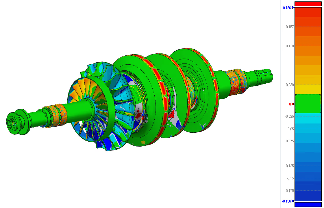
A client needed a replacement rotor shaft for industrial equipment. Original CAD files, drawings, and specifications were unavailable.
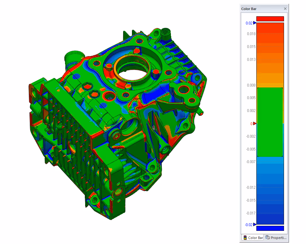
In this case study, we aimed to create a full digital model of an engine casing. This casing had no current CAD files, outdated drawings, and undocumented shapes because of years of use and part changes.

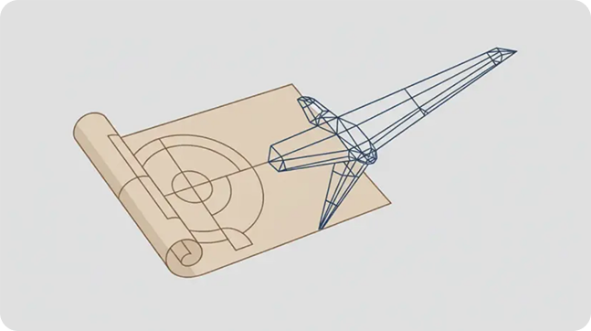
We were recently tasked with recreating a fan housing using only the client’s original paper drawings.

This case study describes how we helped a defense customer turn a dense point cloud into a usable surface model. This model was a CAD surface for an F‑16 that could feed straight into simulation.
On behalf of JJET Enterprises, I just wanted to thank you and Cad / Cam Services again for the great job and quick turn-around time on the job that we sent you. We would recommend you and definitely will be doing business with you in the near future.
James R. Thomas
JJET Enterprises
.svg)

On behalf of JJET Enterprises, I just wanted to thank you and Cad / Cam Services again for the great job and quick turn-around time on the job that we sent you. We would recommend you and definitely will be doing business with you in the near future.
James R. Thomas
JJET Enterprises
“You ROCK and a huge thank you to you and your team for working so diligently to hit our goals.”

Greta Nintzel
Content & Digital Media Associate, Rich Media Team (amazon supply)
Thank you so much for all of your help.
It is greatly appreciated.
Angie
CTR USARMY CCDC ARL (USA)
“CAD / CAM Services has been our source for all CAD related projects over the past 10 years. If it involves CAD conversion or large format scanning, CAD / CAM SERVICES is always our first call.”
Bill Johnson Jr.
Dallas Aerial Surveyors
“CAD / CAM Services provided timely professional consulting advice and guidance that greatly helped us configure our platform for current and near-future expansion needs. Many thanks to Scott Shuppert for all his hard work on this project.”
Richard Schmitter
GTE Media Ventures
“We used CAD / CAM Services for CAD conversion work and it was great! We have already decided to use them for our next project. They did everything they said they were going to do and more. The work turned out well.”

Pete Iannuzzi
Sony Music
“You have been absolutely the BEST Company to work with in my entire career. I almost hate to see us finish our Mylars!”
Jerry McNabb
R Civ USAF – Tinkers Air Force Base
“We used CAD / CAM Services for scanning and converting film and also the purchase and install of IMR’s Electronic Document Imaging Product – Alchemy. They know what they are doing and it has turned out to be a smart purchase for us. We will be adding additional licenses of this product, along with additional scanning and conversion services from them.”

Bill Scott
City of Carrollton
“CAD / CAM Services scanned > 6,000 maps for us and sold and installed a scanner and an EDMS system to our district. It has turned out to be a great investment for our district. We had several competitive firms compete on cost and scanning quality. CAD / CAM Services was the hands-down winner for myself, the engineering staff and the board. We are presently publishing the images on the internet and plan to continue using CAD / CAM Services They treated us fairly and delivered on-time and on-budget.”

Bo Daffin, CTA, RPA
Deputy Chief Appraiser of Central Appraisal District of Collin County
“RISD has been using CAD / CAM Services for years and has no need to consider anybody else. We have used them for scanning thousands of drawings and the install of our engineering/facilities management EDMS system.”
Greg Schulz
Richardson Independent School District
“CAD / CAM Services converted our plant drawings into AutoCAD and they turned out well. We will use them again.”
Phillip Schmidt, Jr.
District Plant Engineering Manager, UPS
“We purchased several Cyco’s AutoManager Workflow licenses from CAD / CAM Services and it has worked out well. We intend to add to this as budget allows”.

Nathan Jones
City of Garland Texas, Engineering Department
“Overall it looked really nice. I definitely like your approach of doing the internals 1st. It really gives me a better idea of what I’m actually programming.”

Shane Duncan
Engineering Manager – W Machine Works Inc.
“CAD / CAM Services was so easy to work with. They delivered our project on time and on budget. I highly recommend.”
Nikko Meyers
Scan Direct
“CAD / CAM Services digitized and converted Electric Utility maps to AutoCAD for our firm. We have been very pleased with the quality of their work and have found CAD / CAM Services to be cooperative and easy to work with.”

Ed Turk
V.P. Cornelius – Pierce Consulting Engineers
“CAD / CAM Services provided timely professional consulting advice and guidance that greatly helped us configure our platform for current and near-future expansion needs. Many thanks to Scott Shuppert for all his hard work on this project.”
Chris Kidd
Dilon Technologies
Learn how to choose a CAD outsourcing partner for aerospace. Avoid costly data translation errors. 35+ years of experience guide your selection.
Learn how to choose a CAD outsourcing partner for aerospace. Avoid costly data translation errors. 35+ years of experience guide your selection.

Take a Look at Our Case Studies! Solidworks as a platform offers two main 2D to 3D pathways; drawing from scratch and remodeling existing ‘.DWG’ and ‘.DXF’ files as 3D models. The functionality of importing an existing 2D drawing and upgrading it into a...
This guide will teach you about 3D CAD viewers and outline considerations to make before picking the right one. We review 5 options and pick a clear winner.
In this guide, you’ll learn how CAD/CAM Services can save you time and money during each digitization project. Digitization can make manufacturing faster than ever before.
This in-depth guide will teach engineers how to use 3D-scanned aircraft files and transform them into manufacturable 3D STEP files with fewer mistakes.
Another common misconception is that BIM is just for massive skyscrapers and huge manufacturing facilities. We made a BIM file for a small company’s garage warehouse, so there is certainly no limit to how big your company has to be.
BIM is for any company that operates a facility. The BIM file will include information that helps you every week by minimizing downtime, improving yield, and maximizing your efficiency. Whether you’re making hand-knitted sweaters or skyscrapers in Manhattan, BIM will help your operation.
Using Revit, yes we do. Think of BIM as an intelligent 3D model of your building. We know exactly where all of the HVAC is, IT cabling, electrical, the cost of doors and windows, when mechanical systems need to be serviced, all the way to a room number with a phone number and IP in that room. In addition to our Ray Tracing technology to support some very life-like photo renderings.
BIM stands for Building Information Model, Maintenance, or Management. We typically say “Model”, since BIM is a technical model of your new or existing building. A BIM file is much more involved and detailed than a 3D CAD file, and the purpose of a BIM file is completely different. BIM files are created to help your projects in multiple aspects. BIM helps with the cost, performance, appearance, logistics, efficiency, and environmental impact of your new construction or existing facility.
In BIM, it’s common for us to talk about 2D, 3D, 4D, and 5D files:
A well-made BIM file can be a lifesaver for any type of company:
Our CAD drafting services have a minimum order price of $195.
With a standard ‘D’ or ‘E’ size 2D AutoCAD *.dwg being $ 195.00. This is a fixed price for almost all 2D CAD work. *There is a small exception for GIS or very dense drawings.
All the CAD file formats are listed on this page but bear in mind that we also work with exotic and legacy CAD systems. After 31 years of providing CAD Services, we have run into almost any CAD file format.
Our facility runs three shifts and we're open and operating 24/7 to ensure the fastest turnarounds on the market. We offer turnarounds as low as 24 hours on our CAD drafting work. For larger projects, we can commit to aggressive timelines and tight turnarounds to ensure you meet your needs.
We like to bill our CAD drafting projects per hour. The rate depends on the CAD software that we use and any specialties or expertise that your project requires. It typically starts at $55 an hour, and you only get billed for hours that went directly to your project (no, you don’t get charged for any time spent daydreaming or working on other projects).
Often, we’ll include a limit to the cost, called a “not to exceed quote”. This will protect your budget and make sure you’re never paying too much.
We can also provide a fixed cost as part of our PO, if you would prefer that route.
To get the most accurate CAD drafting quote, we’ll need the following:
Fill out our quote form, attach your files, or simply send us an email. Tell everything about your project, like the model purpose.
For smaller files < 15 MB you can simply email them to us. For something larger, just drop them in any number of drop boxes like Dropbox, Google Drive, Microsoft OneDrive and others. Or if you would like, just contact us for a private, hardened link.
It is fine to use most any time of compression such as *.zip, *.rar, *.tar, *.7z, *.arc, *.LBR, and even *.iso images.
A direct email is sales@cadcam.org
We also use a hardened OwnCloud web file sharing platform for unlimited file transfers. We provide unique and very private Web Storage Portals, this also supports file syncing for extreme convenience for you. Because so much of our work is DOD or weapons design work, Security – and confidentiality is very important to us.
Yes. NDAs are a common part of our business. All data is yours – not ours, and treated as proprietary data and not for public consumption or use. Probably 70% of our work is under NDA agreements. We can generally get these signed within the day.
It depends on the scope of work:
Simple jobs have a lead time of 48 hours. Larger projects are delivered and invoiced weekly.
Yes, we did back in 2008. We started using Cad Perfect™ back in the early 1990s because all of our customers wanted only real Cad Perfect™ work. Back then the buzz words were terms like machine ready, or DXF Traceover and others.
The problem is, nobody wanted that. They all wanted drawings and models that they did not have to touch. Everybody wanted drawings just as if they hand redrew the work themselves.
Thus, Cad / Cam Services™ was the first company to start offering ONLY Cad Perfect™ work.
Yes we do, and have now for several years. In addition, we also support the industry specific plans as well.
It depends on the complexity of the scanned model and material properties. As, for example, it may be much more complicated to properly scan an object with a reflective surface, than a non-reflective surface. It also depends on three main factors:
Simple quick cell phone photos are worth a thousand words to us. To know for sure you can request a quote. It is of course, free – and treated as if an NDA is already in place.
Some averages:
Because so much of our business is Aerospace related, our scanning – and the completed CAD file HAS to be within ±.005” anywhere on that part, we never use consumer-grade scanners. The scanners we use start at $25,000 and go up to $700,000 (CT) per scanner.
At any given time, we have in excess of $ 5 million just in scanning hardware we use. In addition, a hidden factor of scanning on any system is the assembly and clean up of any scan. The rule of thumb is a 2-1 ratio. So even with our experienced scanning staff, if we spend one-hour scanning; we will then spend an additional two hours of clean up and assembly before our CAD group gets the Point Cloud file to simulate or reverse engineer.
A point cloud is thousands if not millions of data points located in space by X, Y, Z coordinates. Images of this nature are often captured with Faro Focus or Artec scanners that specialize in large-area scanning. Most likely you obtain building and territory plans in this file format.
A polygon mesh is a set of triangles located in the same manner. These scans are obtained with Artec, Creaform, Enscan and other handheld scanners. Parts and reverse engineering device scans are usually polygon meshes.
The scanners we use are as accurate as the industry offers – from anybody at any cost. We use Faro and Artec 3D scanners, in addition to Faro CMM type arms, including the Surveyor tables. Depending on what scanner we use:
The typical AEC D & E size sheet is $225. There are possible discounts depending on the job size. The more you convert the less you pay. The bulk of the files we produce are for AutoCAD.
In order to make an accurate representation, you have to calibrate the original drawing, which may have deformed during its storage period. Non-dimensioned mediums need to be thoroughly calibrated before digitizing.
Parts of scanned data may be lost due to time and other factors. Because it is important to recreate the design intent, we need to recreate lost data.
You ONLY receive Cad Perfect™ files – as if you had drawn these by hand.
Using Revit, yes we do. Think of BIM as an intelligent 3D model of your building. We know exactly where all of the HVAC is, IT cabling, electrical, the cost of doors and windows, when mechanical systems need to be serviced, all the way to a room number with a phone number and IP in that room. In addition to our Ray Tracing technology to support some very life-like photo renderings.
The Department of Homeland Security protocol PPD-21 requirement has deemed that sixteen (16) industries and services are critical to our US Nations security.
These industries require additional security protocols when creating CAD files. CAD / CAM Services follows all of these requirements. Think of industries and info structures such as power, water, along with fourteen (14) other industries. For a full list please see Critical Infrastructure Products.
Mylar films can be stored in climate-controlled facilities. However, films get skewed and change sizes over time – ironically not linear. So what changes on one end, does not apply to what is in the middle, or the other end. We have seen ‘J’ size Aerospace Mylars (about 48×180”), vary by a full inch.
CAD/CAM Services utilizes a proprietary process to make Mylar raster images dead on a 5” or 10” grid. Our process was developed in conjunction with, and approved by Boeing engineers.
Per hour. Hourly rate depends on what CAD software used and typically starts at $75 per hour. In general, to make this process safer for you, we often provide you a fixed not to exceed the cost as well. That way, you are protected from an open-ended PO. However, the reality is our fees are based on time. In addition, services in say Catia or NX are more expensive than say Solidworks. Or, simulation services are commonly done by real engineers.
First of all, we need to know the target CAD system and whether you have an existing template, or set of CAD standards for this project.
The main question is the overall complexity. As each part and assembly consists of different features and elements the best way is to provide us with an example. Again, a picture is worth a thousand words.
If you already have a model and need us to improve it or update it in any way we need to know which dimensions and features are critical and which can be modified to achieve your desired result. Even a before and after example works very well. We started with x, and got to this CAD file.
We can also offer you better options if you provide us with the purpose of your project (demonstration, 3D printing, FEA Simulation, CNC manufacturing, etc.). This helps us better refine the task.
We create 2D drawings from our 3D models for QC purposes. We follow aerospace standards and deliver ±.005” accuracy models for all projects. All of our QC is done by a different person than the designer. On Catia work, we often use Q-Checker for Airbus.
We have a minimum order fee $150.
We need to know whether you need your parts to be scanned by us. Or many times we can work with 3D scans provided by third-party companies. The quality of the scan is everything in our business. Anyway, we strongly advise you to use us for both the scanning and the CAD conversion aspects. That way, we can control the quality. Sometimes we receive poor quality scans which make it impossible to create truly Cad Perfect™ models for you. By all means, send us a couple of even cell phone photos, and the rough size of the object. Most of the time, this will provide us enough information to provide a real bid.
The price depends on the part complexity, size, as well as the target file parametres. We need to know whether you need full parametric models, and your desired accuracy. If you tell us the purpose of reverse-engineered models, we can often provide you with possible solutions. The target CAD software may change the price as well. This includes sophisticated Workstation add-on products such as Composites, Catia electrical wiring, mold design, and others.
Reverse engineering is the process of analyzing an existing physical object, product, component, assembly, or system to understand its design, dimensions, materials, and functionality so it can be recreated, modified, documented, or manufactured again.
In the CAD and engineering world, reverse engineering typically involves converting a physical part into accurate 3D CAD models, 2D drawings, and engineering documentation.
We often: 1) Capture Existing Data by 3D scanning, 2) create a Digital model, often called a Point Cloud, 3) build a 3D model, and 4) produce the required engineering documentation.
Typical Accuracy Ranges
Hand Measurements (Calipers, Micrometers) ±0.001" to ±0.010"
Structured Light Scanning ±0.001" to ±0.005"
Laser Scanning ±0.002" to ±0.010"
Photogrammetry ±0.010" to ±0.100"+
CMM Measurement ±0.0001" to ±0.001"
Hybrid Scan + CMM Validation ±0.0005" to ±0.002"
For aerospace, medical, and precision manufacturing applications, a combination of 3D scanning and CMM inspection is often used to achieve the highest accuracy.
Also, there can be two parts to this answer: 1) The accuracy of the scanner, and then 2) if we are going all the way to an editable feature-rich CAD file. If we are going all the way to the CAD file, we are within ±.005” of any Point Cloud data.
Many people use the terms 3D scanning and reverse engineering interchangeably, but they are not the same thing.
3D scanning is the process of capturing an object's geometry. Reverse engineering is the process of converting that captured data into usable engineering information, such as CAD models, drawings, and manufacturing documentation.
Simple Explanation
Think of it this way:
A 3D scanner captures the shape of an object. Reverse engineering transforms that shape into an intelligent, editable CAD model that engineers and manufacturers can use.
Yes. Reverse engineering obsolete parts is one of the most common reasons organizations pursue reverse engineering services.
When original manufacturers no longer support a component—or when CAD files, drawings, tooling, and engineering records have been lost—reverse engineering can recreate the engineering data needed to manufacture replacement parts and extend the life of critical equipment.
Why Obsolete Parts Need Reverse Engineering
Organizations often face situations where:
Rather than replacing an entire machine, reverse engineering allows companies to reproduce the specific component that has become unavailable.
We need to know source CAD and target CAD software. Since large quantity orders can be discounted by us you can provide us with the number of parts you need to be converted.
If you tell us the desired purpose of the conversion we can offer you some conversion options. We can also convert your files into vendor-neutral file types (.STEP, .STL, etc,).
Please email us even cell phone photos, and the rough size of what you wish scanned and converted sales@cadcam.org.
You get native Cad Perfect™ files with the full-featured model tree (where applicable, since some file types have no trees), and features can be fully parametric. It all depends on your goals. We prefer to not translate any files. Our goal is to deliver to you a file that you do not have to touch. Our work is exactly as if you had reproduced that work in-house.
All the CAD file formats are listed on this page but bear in mind that we also work with exotic and legacy CAD systems. After 31 years of providing CAD Services, we have run into almost any CAD file format.
We support all the modern CAD systems including SolidWorks, Catia, Siemens NX, PTC Creo, Inventor, Revit, AutoCAD, and many others.
Yes, absolutely. We can perform legacy CAD conversions. Just send us some example files, and what CAD system we need to wind up in, and let us design the best solution for you.We have worked with old Computer Vision tapes, Anvil, and many other 1980’s systems.
A Finite Element Analysis (FEA) is a form of non-destructive testing (NDT) that shows how your part reacts to real-world loading events. A common example is running an FEA on a support bracket. The FEA will give results showing how much the bracket deflects, how much reactive force is seen, and the kind of internal stresses the bracket experiences.
FEA results will change dramatically based on the position and angle of the load, how much force is applied, the material properties of the part, and the design of the part itself.
An FEA is used to optimize a part before manufacturing begins. It allows you to find weak points within your part or assembly, and it will predict a failure before you physically make anything. This gives you an opportunity to fine-tune each part to optimize its size, strength, and cost before you start producing it.
The more information we have, the more accurate the simulation results will be. It also depends on what type of simulation you want to run. For a simple FEA, we can run an accurate simulation with just a 3D CAD model and loading/force/pressure information that you want to simulate.
Don’t have a 3D model? Not a problem, our team can make one for you from scratch, and then run an FEA on it.
For a more detailed answer, a well-run FEA will need:
• Material properties: What material is the part made out of? We can run different FEAs with different materials to help you pick the right one.
• Loading conditions: The size, location, and type of load you want to simulate.
• Bonding condition: How is the part held in place? Is it bolted, welded, or just sitting on a tabletop?
• A 3D model
• For other simulations: Please provide us with all thermal, dynamic, aero, and/or fluid flow information. Feel free to call us and we’ll walk you through what we need.
You bet we can. We created millions of files for Amazon’s online catalog, so no doubt we can help you. Click Link 1, Link 2 or Link 3 for some live Amazon examples. Simply select any file type from the list under the photo.
We directly support TraceParts.com, PartSolutions, GrabCAD, and several others.
There are no limits to creative tasks. Contact us and we will work something out. This includes part animation, expanded views, opening up assemblies, and full digital mock-ups.
We can stage what you want, or propose to you with our exclusive cinematic masterpiece.
.svg)
.svg)
.webp)
.webp)

.webp)
.webp)
.webp)


.webp)
