How to Build an Aircraft Model by Converting 3D-Scanned STL Files into Functional 3D STEP Files
Getting a 3D scan of your aircraft model is a great first step, but it still leaves you pretty far from a manufacturable model. Machine shops often require STEP files to start working, and they won’t be able to accept your STL files. Even worse, going from an STL to a functional STEP file takes more than just one click.
In fact, the conversion process can take longer than the entire 3D scanning process. If you make a mistake along the way, you’ll face even bigger delays and cost sinks.
Our experts at CAD/CAM Services put together this quick guide to show you exactly how to build an aircraft model by converting 3D-scanned STL files into functional 3D STEP files.
Why Convert STL to STEP for Aircraft Models?
An STL file works well for 3D printing, but it doesn’t help an engineer beyond that. These files are often difficult to open with CAD programs, don’t have any parametric data, and cannot be edited or changed at all.
If you’re building a digital library or archiving your parts, they need to be in a CAD-friendly format, like a STEP file. STEP files are universal parametric models that can be used across CAD programs, can be opened and viewed easily, and give you the ability to pull dimensions and make changes.
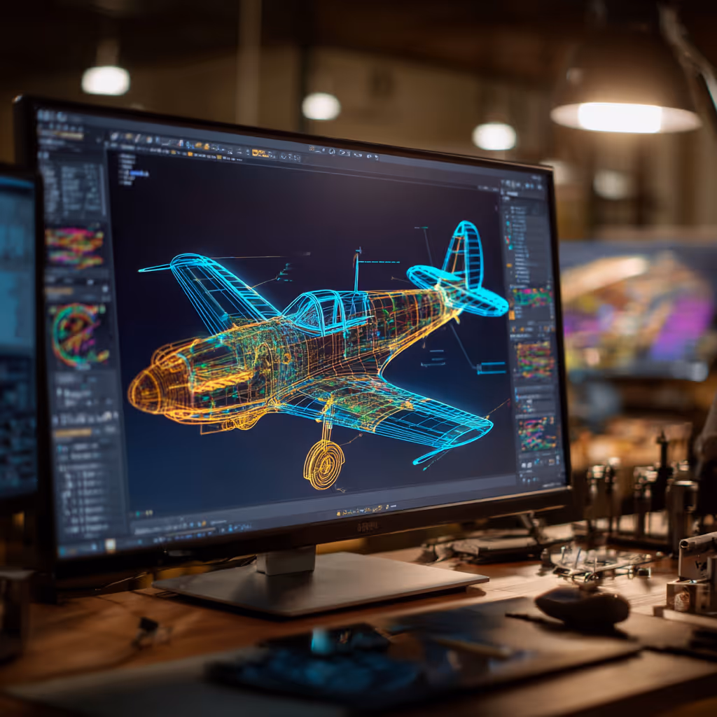
Understanding the Differences: STL vs STEP Formats
An STL file is a mesh-based file, essentially a collection of points with lines connecting them. STEP files hold a lot more data, and they are true 3D models. STEP files can be opened in most CAD platforms and they carry metadata and parametric information.
Prepping the 3D Scan: Cleaning and Optimizing Your STL
Before you start the conversion, you need to prepare your 3D-scanned model. Open the file and fix any defects: holes, missing corners, faces with gaps, and any other mistakes you spot. You can use a program like MeshLab or GOM Inspect to optimize the mesh density and clean up errors before you continue.
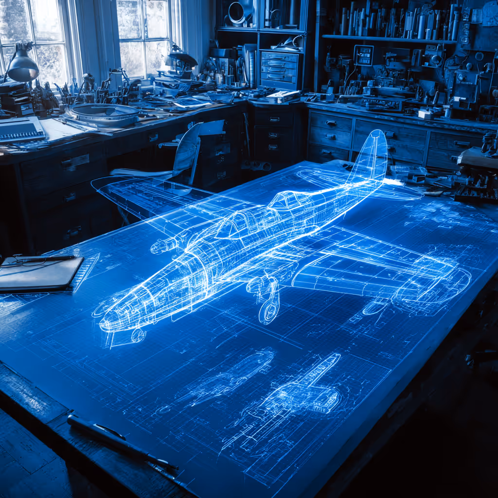
Reverse Engineering: Rebuilding CAD Geometry from Mesh
One big issue is that you cannot export an STL file into a STEP file and create physical properties and 3D data. Since the STL is a series of triangles and points, you might need to trace over the scanned file using NURBS surfaces or parametric CAD.
Reconstructing Aircraft Features: Wings, Fuselage, and Detail
What about complex features that aerospace engineers run into, like wings, a fuselage, and landing gears? For these parts, you’ll need to use a 3D CAD program to reconstruct each part very carefully.
Assembling the Full Aircraft Model
With each aircraft component modeled into STEP or native CAD files, you can start assembling the parts. The assembly will be comprised of a series of individual components, and they need to be aligned, constrained, and arranged correctly.
Validating the Geometry: Accuracy and Tolerances
Now that your aircraft model is assembled, it’s time to check for accuracy and tolerances. We like to overlap the created CAD file over the scanned STL mesh to look for deviations and mistakes.
Real-World Applications: From Legacy Restoration to 3D Printing
Using this STL to STEP conversion process has helped a lot of aerospace companies in the past. In one project, we took 3D scans of entire F35s and converted the meshes into functional CAD models.
Conclusion
With us, you can bring your legacy aircraft components back to life. We can handle the entire STL-to-STEP process, and you’ll be able to save time and money with our team. With nearly 100 engineers and designers on our team, CAD/CAM Services can offer you faster turnarounds and better prices than our competitors. Get a free quote today.
Recent Posts


6 Easy Steps to Convert a 2D to 3D Model Using SolidWorks
Take a Look at Our Case Studies! Solidworks as a platform offers two main 2D to 3D pathways; drawing from scratch and remodeling existing ‘.DWG’ and ‘.DXF’ files as 3D models. The functionality of importing an existing 2D drawing and upgrading it into a...

Tips for Picking the Perfect 3D CAD Viewer for Your Needs
This guide will teach you about 3D CAD viewers and outline considerations to make before picking the right one. We review 5 options and pick a clear winner.
In this guide, you’ll learn how CAD/CAM Services can save you time and money during each digitization project. Digitization can make manufacturing faster than ever before.