Converting Point Cloud to CAD Mesh STL – 5 Tips
Take a Look at Our Meshing Case Study!
To obtain a proper STL file, you need a program that triangulates the points to create the appropriate vectors. The shell created in STL is what the cutting machine slices. Here are a few tips, as outlined below.
Point cloud processing has improved how machines read real-world input, a file consisting of 3D scanned coordinate data. They can be used for applications like reverse engineering, quality inspection, BIM and complex CAD modeling. Other uses are terrain studies, cultural heritage documentation, forensics, animation, VR, face recognition, the list goes on and on. A polygonal mesh is a surface data based on triangulated points. For most CAD/CAM and modeling applications, having a well-defined mesh is vital. If you are working with a point cloud, you must convert it into a mesh. Depending on the case, it can be a tough process; but we’re here to help you with 5 tips for converting your point cloud into a mesh, focusing on the STL format.

(Courtesy of Shutterstock.com)
Converting Your Point Cloud to a CAD STL Mesh – 5 Tips
Point cloud processing has improved how machines read real-world input, a file consisting of 3D scanned coordinate data. They can be used for applications like reverse engineering, quality inspection, BIM and complex CAD modeling. Other uses are terrain studies, cultural heritage documentation, forensics, animation, VR, face recognition, the list goes on and on.
Why Polygonal Meshes? The STL File
A polygonal mesh is a surface data based on triangulated points. For most CAD/CAM and modeling applications, having a well-defined mesh is vital. So, if you are working with a point cloud, you must convert it into a mesh. Depending on the case, it can be a tough process. But we’re here to help you with 5 tips for converting your point cloud into a mesh, focusing on the STL format. An STL file is the most standard and wide-spread mesh format. Originally made for additive manufacturing, it remains as the main option for printing models.
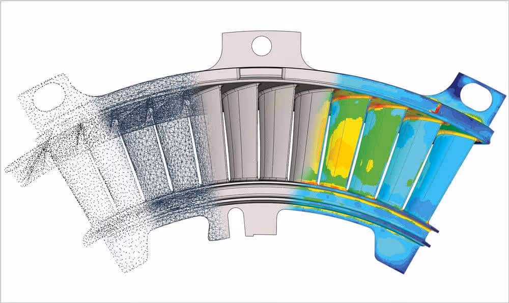
An illustrative flow for the reverse engineering process. A point cloud obtained from a scanned object > Triangulated into an STL mesh > Engineered into a parametric CAD solid > Lastly, the model can be simulated for quality control, generative design, further modifications on its parameters and encoding for CNC and additive manufacturing. (Courtesy: canadianmetalworking.com)
Tip 1: Define Your Objective
Converting 3D scanning data can either be a pretty fast and kind of an automatic process, or, in contrast, very complex labor. Some applications will deal with simple shapes for small objects, while others might involve large files with millions of points and noisy data. Depending on the complexity of data and dirtiness, you’ll need to work with a set of features and filters, like decimation and denoising, and tools for closing gaps and cleaning.
Regarding the STL file, you should be aware of its limitations, which lacks in storing color and texture data. That means some purposes like animation or image rendering will not apply for this particular mesh conversion. On the other hand, if your objective is taking a scanned mechanical part for reverse engineering, quality control, or manufacturing processes like 3D printing, then STL is the format to work with. The following are some common software that may be what you’re looking for your project:
- Geomagic Wrap: One of the top pro choices for point cloud processing workflows. Developed by 3D Systems, one of the leading companies for 3D technology engineering, development and services (Also known for patenting the first 3D printing technology and the STL format itself). Geomagic Wrap offers a set of cutting-edge tools for producing flawless and accurate results.
- Geomagic Design X: What makes it highlight is its specialized interface for reverse engineering as a whole. Its features allow for efficient integration between point cloud processing and CAD.
- Autodesk Recap: Specialized for LiDAR scanning (aerial). It’s great with registering point coordinates and processing heavy data and large files efficiently.
- Artec 3D Studio: The inhouse software for Artec 3D scanners. Artec 3D is one of the leading brands for high-quality scanning on a wide variety of industrial level uses. Artec 3D Studio offers many tools with solid workflows for point cloud processing. It’s ideal for users of this family of scanners, where point registration can be integrated, monitored and automated during the scanning process.
Tip 2: Pay Attention to Data Recollection
Try to simplify your data! Point cloud processing is a very complex set of algorithms that can be very demanding on your computer capabilities, crashing is very common with this kind of data. So, you have to know where your restraints are and what you can do to improve your hardware. Once you get the raw scan, try to reduce the most redundant data to get the lightest file size possible for your purpose. One of the best practices to increase conversion speed, accuracy and efficiency, is to generate ordered data with grid patterns – it will all depend on the specific tech you’re using.
Though investing in a good scanner or camera is important, it’ll not guarantee a good scan. Taking the best practices is crucial (position, number of shots, surroundings, surveying control, point registration). The more scans you make the better, as they can be overlapped for better resolutions and thus avoiding gaps and holes. Just by taking into account these considerations can save you a lot of time and energy.
Tip 3: Check STL Quality
For most STL applications, mainly manufacturing, the slightest error on its surface can be a mess. The issues you should be aware of are:
- The STL is not watertight: The inner volume for the STL must be fully defined. It mainly happens because your mesh has holes and gaps that must be closed.
- Wrong normal orientation: Triangle orientation is defined by normals, make sure they all point outwards.
- Intersecting triangles: This can happen after a processing error or because of mesh distortions.
- Overlapping surfaces: Some files are produced with different overlapping bodies. Also known as non-manifold geometry, the software understands it as two different volumes filling the same space. All separate volumes must be merged into one to avoid manufacturing failures.
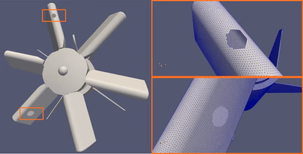
An example of mesh repairing (Courtesy: conself.com)
Tip 4 Defining the best workflow for you
Since point cloud processing software have several functionalities, it can lead to time-consuming errors if the intent is not clear enough. From a productivity point of view, defining a consistent stream of tasks is essential for faster and more efficient operations with a solid troubleshooting plan. We believe the best way to illustrate this, is with an example. In this case, for Geomagic Wrap:
- Import: Open all your point cloud files generated from the same object. On the “Model Manager” tab to the left, you can manipulate views, edit a specific set of data and arrange your files into group folders.
- Registration: To reconstruct an accurate depiction of the object, scanned data must be perfectly matched with each other. The approach for this workflow will be manual, so the “Manual Registration” tool must be used (Alignment > Scan Registration > Manual Registration)
By selecting reference points between a fixed set and a floating one, the software algorithm will start to recognize the intended alignment. Finally, the “Global Registration” tool can be used to iterate between geometric patterns to reduce deviations to a minimum. Floating data and outliers can be cropped with the selection tools.
- Merge: Once everything is ordered, you can create the mesh. Geomagic offers the “Merge” tool (Points > Combine > Merge). The “Merge” window offers many settings for reducing noise data and options for defining the maximum number of polygons. If this number is reached, the software will automatically decimate points.
- Repair: Once we get the mesh, we must apply the criteria seen on tip 3. Many errors may be seen directly, but some details will be troublesome to get with the eye. The “Mesh Doctor” tool (On the “Polygon” tab) will analyze the status of the mesh and will point out all the details that must be fixed. The “Polygon” tab offers a variety of tools for this purpose. Just to mention a few, the “Fill Holes” set of tools offers many approaches for defining a suitable closed surface, “Defeature” can reduce spikes and bumps and “Decimate” can further reduce the number of triangles.
- Align: The model is ready, but it’s still floating. To fully define it, the object must be aligned with the world coordinate system. Many geometry reference tools on the “Feature” tab like planes, lines, points and cylinders can be used to define vectors within the object. To fix it, the “Align to World” tool in the “Alignment” tab does a perfect job.
- Export: Save the mesh as an STL file.
This example is one of many paths that can be taken, defining which one is the best for you will add greatly to efficiency.
For a reverse engineering approach, Geomagic suggests this decision tree.
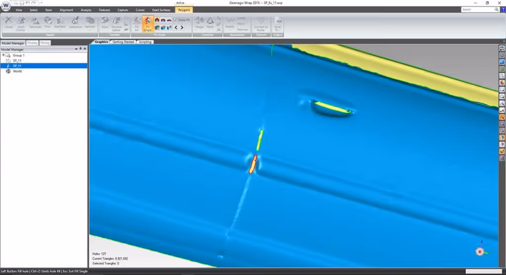
The Geomagic Wrap interface. (Courtesy: laserscanning-europe.com)
Tip 5: Optimize Your Process
You can further optimize your workflow by using plug-ins. Using point cloud processing plug-ins to your CAD software can make your meshing and exporting process faster. For instance, if you are a SolidWorks user, there’s a Geomagic plug-in that works perfectly for an integrated workflow. Furthermore, try using scripting and macros to automate repeated tasks, once you identify them. If you want to optimally develop your process, this is a strong option.
CAD/CAM Is Here to Help
CAD/CAM Services has been providing high-end outsourcing scanning, reverse engineering and point cloud conversion services since 1988. Please, feel free to visit our webpage for more information on our wide catalog of products and services.
Recent Posts


Tips for Picking the Perfect 3D CAD Viewer for Your Needs
This guide will teach you about 3D CAD viewers and outline considerations to make before picking the right one. We review 5 options and pick a clear winner.

In this guide, you’ll learn how CAD/CAM Services can save you time and money during each digitization project. Digitization can make manufacturing faster than ever before.

How to Build an Aircraft Model by Converting 3D-Scanned STL Files into Functional 3D STEP Files
This in-depth guide will teach engineers how to use 3D-scanned aircraft files and transform them into manufacturable 3D STEP files with fewer mistakes.