Robotics Design Using CAD

From where we sit, it looks like Robotics has become an essential part of all industrial activities. The introduction of Robotics has made life easier. Robots are reprogrammable devices that are used to perform various day to day tasks. Robots can deliver outputs that are accurate, consistent, and less time-consuming. They perform in any type of environment without any deviation from delivering desired outputs. Robots can even perform tasks which are very dangerous to humans with ease.

The designing of robots has become a daunting task for designers. The customization of these robots is increasing at a brisk pace. Each customer has their own requirement. Also, designers have a tough task in addressing industries ranging from children’s toys to Robots used in the medical field. The list of industries using robots is increasing at a brisk pace, which in turn increases the demand for the design of Robots.
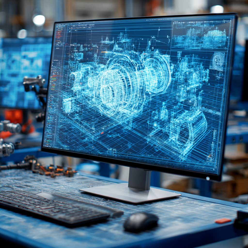
We are familiar with CAD (Computer-Aided Design), CAM (Computer-Aided Manufacturing), and CAE (Computer-Aided Engineering). The introduction of CAD has brought a massive turnaround in the design part of Robotics. Using 3D CAD Software, a 3D model of a robot can be easily created with all its geometrical parameters. These 3D models can be easily customized based on the requirements or changes provided by the customer. CAD Design enables designers to see the 3D robotic model from various angles and check if they align with the geometric parameters provided. CAD allows the designer to make corrections with precision.
CAE is used for simulation of the design developed in CAD. CAE is basically used for verifying the design. CAM programs are used for Manufacturing. Using CNC or DNC codes CAM controls the robot.
Robotic Arm – A widely used Industrial Robot:
A robotic arm is the most commonly manufactured robot that is designed to perform any task such as welding, gripping, and other industrial equipment plants. An industrial robotic arm resembles a human arm. The end part of the arm known as an effector (Gripper) is designed to perform various tasks. Depending upon the nature of work the gripper is designed to perform that particular task.
Various Types of Robotic arms:
- Cartesian Robot: It has three joints. This robot is mainly used for performing tasks such as moving, painting, welding, etc.,
- Articulated Robot: This type is used mainly by performing various types of welding, spray painting, assembly operations.
- Spherical Robot: It performs tasks such as Fettling Machines, gas welding, arc welding, die-casting. It is also used for handling machine tools.
- Parallel Robot: The main use is for mobile platforms handling cockpit flight simulators. Its arm has concurrent prismatic or rotary joints.
- Anthropomorphic Robot: This robot is designed in the way to resemble the human hand. It has got independent fingers and thumbs similar to that of a human hand.
- Cylindrical Robot: Mainly performs tasks such as spot welding, die casting, handling at machine tools, gas welding, and arc welding.
- SCARA Robot: Tasks such as handling machine tools, pick and place work, assembly operations are performed by this robot.
In robotic arms an important term one has to know is its Degrees of Freedom (DOF). Each DOF is a joint on the arm, a place where it can bend or rotate. Depending on the application of the robot, the DOF is provided during the designing of the robotic arm.
3D Modeling of Robotic Arm using CAD:
Inputs
The basic inputs required for 3D modeling of a robotic arm are:
- A design Drawing
- Analysis Data.
Outputs
The output will be delivered in formats:
- .sldprt and .sldasm
- .iges
- .stp
- .dwg
Depending on the application of the robotic arm, changes can be made in its design.
Recent Posts

Tips for Picking the Perfect 3D CAD Viewer for Your Needs
This guide will teach you about 3D CAD viewers and outline considerations to make before picking the right one. We review 5 options and pick a clear winner.
In this guide, you’ll learn how CAD/CAM Services can save you time and money during each digitization project. Digitization can make manufacturing faster than ever before.
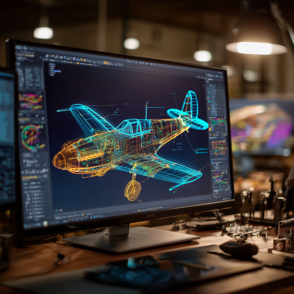
How to Build an Aircraft Model by Converting 3D-Scanned STL Files into Functional 3D STEP Files
This in-depth guide will teach engineers how to use 3D-scanned aircraft files and transform them into manufacturable 3D STEP files with fewer mistakes.