How to Convert Aerospace Drawings from Mylar to CAD
Converting Mylar to CAD, even 3D CAD is a piece of cake…If you know what you’re doing! (We do – learn about our CAD conversion services!)
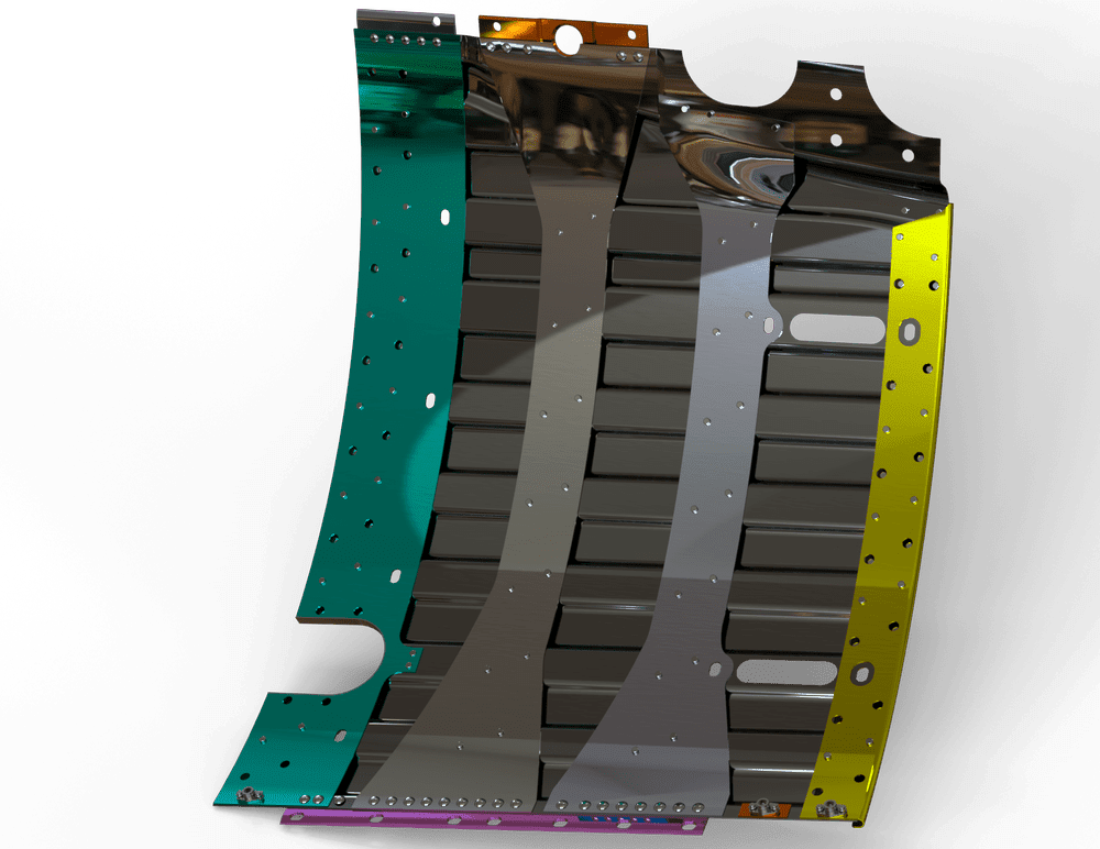
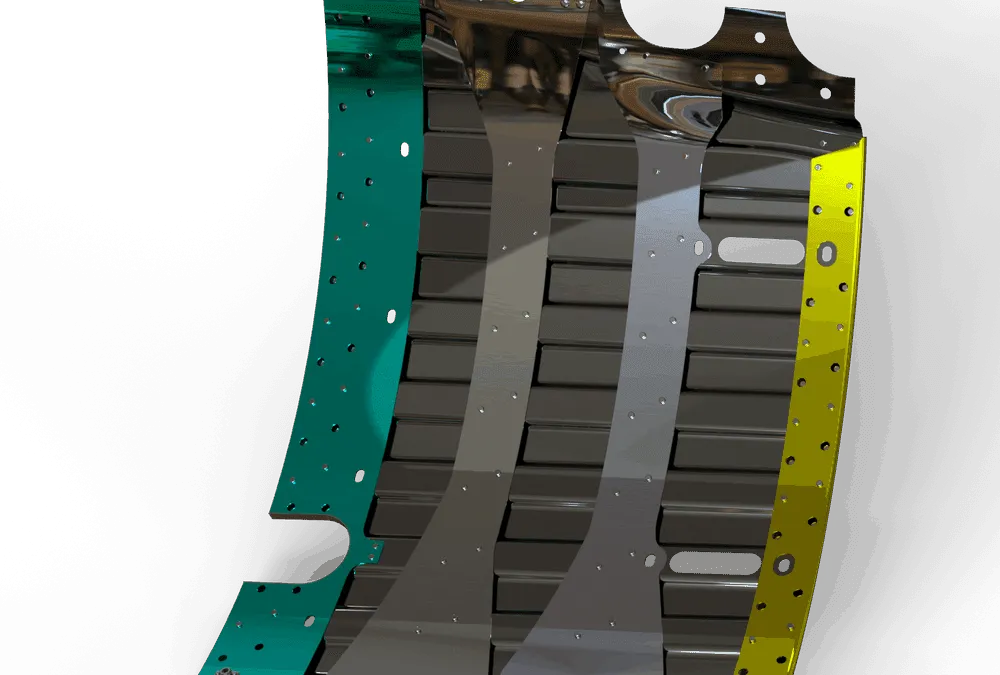
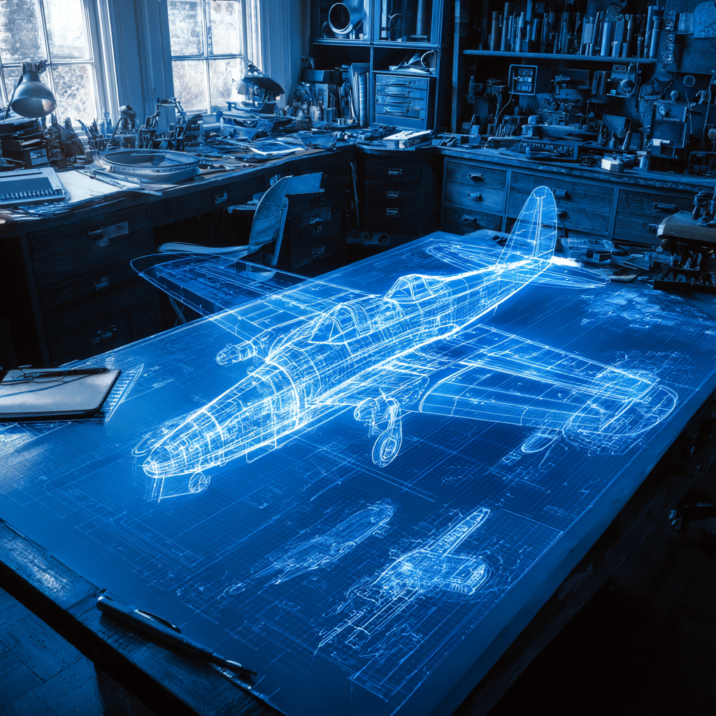
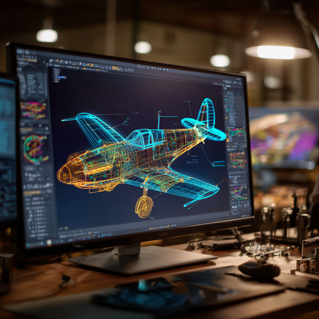
3D Model From Converted Dimensionless Mylar
What is Mylar?
Mylar® is a brand name for a type of stretched polyester film. Mylar (Melinex and Hostaphan) is a polyester film BoPET (Biaxially-oriented polyethylene terephthalate) that is made from stretched polyethylene terephthalate (PET). Mylar drawings are used in engineering and construction because it is more stable than paper.
While Mylar was used for long-term engineering and construction drawings because it was more stable than paper, over time, it too degrades, and the accuracy of the drawing on it can be negatively impacted. Mylar is still sometimes used for printing CAD drawings. That’s because when a printed drawing is required, schematics on Mylar reflect the depth and dimension of the finished project more easily than blueprints or diazo prints.
Moving Into Aerospace CAD with Mylar Drawings
Of course with the advancement of CAD programs, and, especially 3D modeling, many companies today are in the process of taking their un-dimensioned drawings on the stable-based material (Mylars) and preserving them by fully integrating the legacy Mylar drawings into the automated work environment through digitization and subsequent storage capacities.
The aerospace industry is particularly interested in converting these drawings because of the long life of aircraft and the required upkeep, maintenance and parts replacement that is necessary for safe operation.
Some aerospace drawings were originally created and stored on mylar sheets, so there is no underlying CAD drawing to refer to. Even Mylar drawing paper, when it is old enough will deteriorate, and since these very old drawings have no associated CAD file, it becomes necessary to scan and convert them into CAD drawings in order to preserve them.
CAD drawings have the advantage of being easier to store, access, transfer, and retrofit than Mylar or paper drawings. Often, in today’s military and business environment, success depends upon the speed with which information can be deployed. Generating 3D models from the Mylar drawings also makes it far easier and faster to upgrade aircraft parts and systems.
Ensure Success for Aerospace Mylar Drawings
One organization that has successfully converted its aircraft engineering drawings is Tinker Air Force Base’s Engineering Data Support Center (EDSC). Their overall goal was to fully integrate legacy Mylar aircraft engineering drawings into the automated CAD work environment through digitization or scanning and conversion to CAD. Their success was directly attributed to the accuracy attributed to the project.
Transferring Data:
A frequent problem encountered in this transferring data from Mylar or paper into 2D or 3D CAD (especially with aircraft blueprints, engineering drawings, and other projects that require extremely high accuracy to maintain safety) is finding a way to maintain a very precise tolerance of +/-.005″ accuracy over any five- or ten-inch area for the digital scanned files.
Temperature:
Especially when dealing with very old Mylar sheets, there is always a concern that they may have been exposed to extremes of temperature. Heat may have made the older drawings stretch, often with a corner-to-cross-corner loss of accuracy (referred to as rubber sheeting). This stretch affects the overall accuracy of the drawing or otherwise changed in size, affecting the accuracy of the drawing itself.
Un-Dimensioned Drawings:
Moreover, Aerospace Mylar drawings are “un-dimensioned.” An un-dimensioned drawing presents the engineering definition graphically without the use of numerical dimensions. Sizes and relationships of un-dimensioned features are determined by scaling the original drawing or by scaling a stable reproduction made from it. Un-dimensioned drawing forms are identified by the letters PCM or “Photo Contact Master.” Effectivity notes indicate part replacement, upgrades, and modifications for various models.
All of these features must be taken into consideration during the conversion process since the accuracy of the final CAD file is of paramount importance.
The methods used for scanning (digitizing) and converting are critical, and we can help you. Learn more about our 3D scan to CAD services.
Recent Posts

Tips for Picking the Perfect 3D CAD Viewer for Your Needs
This guide will teach you about 3D CAD viewers and outline considerations to make before picking the right one. We review 5 options and pick a clear winner.
In this guide, you’ll learn how CAD/CAM Services can save you time and money during each digitization project. Digitization can make manufacturing faster than ever before.
How to Build an Aircraft Model by Converting 3D-Scanned STL Files into Functional 3D STEP Files
This in-depth guide will teach engineers how to use 3D-scanned aircraft files and transform them into manufacturable 3D STEP files with fewer mistakes.