CATIA CAD-CAM Mold Design Tips and Tricks
Dassault Systèmes CATIA is a powerful 3D CAD-CAM software. Models created in CATIA are widely used in the aerospace and automotive industries. CATIA is a 3D computer-aided design (CAD) program capable of handling large numbers of mechanical parts in its assemblies.
All this data can be stored and managed by a product lifecycle management system. In addition, effective memory management in CATIA enables designers to create intricate designs that usually can not be appropriately processed by its competitors.

Sample model (CATIA Mold Design)
CATIA V5 mold design process requires some preparation. There are different ways of mold design in CATIA.
These ways usually depend on the source files and the required result. For example, mold design in CATIA can be based on 2d drawings, 3d model files, or PDF technical papers.
Correctly made CATIA projects contain all the required dimensions in the feature tree. This time-proven approach is called parametric modeling. All of our designs (including those done with other CAD software packages) are created that way. Following these basic principles enables CATIA CAD designers to swiftly adjust various sketches and features, giving the ability to change angles and diameters on the go.
Designing Mold in CATIA is done in several steps.
1 – Source Data Preparation
2 – 3D Model
3 – Tool Form Creation
1 – Source Data Preparation
CATIA can import various open CAD standard file formats. The best-case scenario is when you already have the geometry saved in a neutral file format (STEP or IGES). In this case – you can skip the model creation process and move on directly to the tool form creation step.
However, in most cases, all you have is an old paper drawing, which needs to be properly digitized. Then, when the source paper or Mylar medium was turned into the electronic format, it is possible to begin 2d to 3d conversion process.
Generally, conversion involves importing the scanned medium into CATIA. This process is quite simple since CATIA can easily import 2D drawings as PDFs. Although, you should keep in mind that this is valid only for properly calibrated and sized imagery cases.
CATIA 3D drawings from PDF are done the same way and are the next step of this very same process.
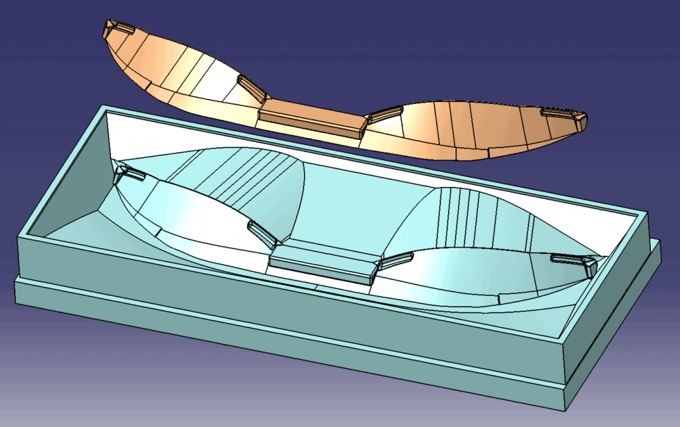
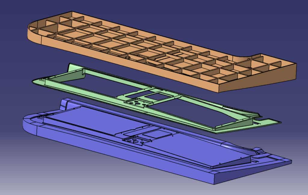
2 – 3D Model
Mold Form for Sheet Metal-like Part
As a representative of the world of high-end 3D CAD, CATIA offers tools for professional 3D model creation. Like most other 3D CAD-CAM systems, CATIA offers designers the feature tree approach, making it easy to create CATIA projects based on the dimensions. Such projects can later be altered or used to develop dependant geometry like mold tools in our case.
Like any other professional software, it requires designers to follow some rules that make it easier to achieve the best results and scale the projects. Like every other professional community, it has its dos and don’ts, which can dramatically change your design approach when you know them in advance.
If you are new to the world of parametric modeling, the user interface of the CATIA drafting workbench may look intimidating. The first piece of advice is to separate sketches and avoid repeating and cloning a pattern or shape design inside the sketch. Relying on features built into the software can save you a lot of time and effort.
It is much better to use the pattern tool provided by your CAD software so that you will be able to easily adjust the basic sketch and all of its children with one operation without the need to find all the instances and adjust them manually. For example, never try to make a plane from a solid face since all the changes in the face may shift the plane or change its angle, affecting all the features linked to the plane.
3 – Tool Form Creation
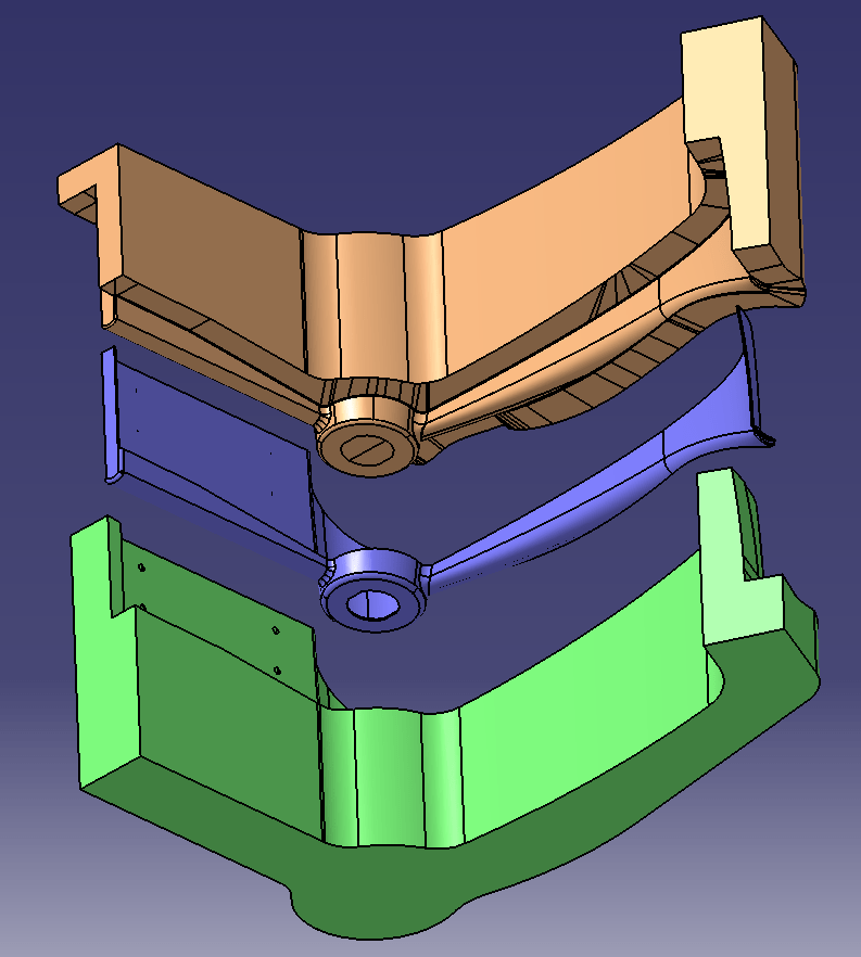
Engine Part Mold Form
Once you have the required CAD files, you can start creating an assembly. The first thing to remember while creating assemblies is to position all the Contextually linked parts to the common origin.
Since we will create a mold in CATIA, it is crucial to determine where the parting lines and gates will be and define the number of gates to fill the part correctly. This process is individual for each part’s geometry, as it considers the cross-sections, overall part size, and whether it contains small elements and narrow paths on the way of the flow.
When creating a mold design, it is crucial to give a drafting angle. This is required for the proper part ejection from the mold form.
As you can see, this part requires a lot of decision-making, as there may be some factors not represented in part geometry itself. After all, CATIA is a 3d program, and it doesn’t know the exact mold process you have in mind for this particular part.
The material type also determines the shrinkage you should keep in mind while designing the mold form. Particular mold flow simulation environments can simulate this and other factors.
It will be possible to create a complete engine design in CATIA with experience, accurate rules, and professional CATIA drafting approaches.
Recent Posts


Tips for Picking the Perfect 3D CAD Viewer for Your Needs
This guide will teach you about 3D CAD viewers and outline considerations to make before picking the right one. We review 5 options and pick a clear winner.

In this guide, you’ll learn how CAD/CAM Services can save you time and money during each digitization project. Digitization can make manufacturing faster than ever before.

How to Build an Aircraft Model by Converting 3D-Scanned STL Files into Functional 3D STEP Files
This in-depth guide will teach engineers how to use 3D-scanned aircraft files and transform them into manufacturable 3D STEP files with fewer mistakes.