By clicking “Accept All Cookies”, you agree to the storing of cookies on your device to enhance site navigation, analyze site usage, and assist in our marketing efforts. View our Privacy Policy for more information.
If you have a Faro point cloud file (.fls), we can post-process all the RAW data you have and build a parametric 3D model representing the scanned area or part.
Usually, post-processing takes twice more time than the original scanning procedure. So spending 5 hours scanning something, it is not uncommon to spend an additional 10 hours cleaning up and assembling the scan data. So if you want the most accurate conversion – contact us. GeoMagic tools are our products of choice. We can provide you with .005” aerospace accuracy Cad Perfect™ models of your design.
These tasks are usually associated with BIM modeling but we can make some precise CAD measurements to help you with further development process.
By outsourcing the time-consuming point cloud conversion, your designers and CAD operators are free to work on new projects, while we create the digital model that exactly replicates the scanned object(s). You simply need to send us your point cloud data, and we will align and edit it to create a finalized, current, accurate, and complete 3D model.
GET A QUOTE
We can even help you recreate entire train cart designs!
Polygonal Models and Dumb Solids
3D scanning and the resulting point cloud data are particularly appropriate for modeling organic (freeform) shapes as well as polygonal models (STL Files) and Rapid NURBS Dumb Solids.
A Polygonal Model is a faceted (or tessellated) model consisting of many triangles. Facets are formed by connecting points within the point cloud. STL files can be used for visualization, rapid prototyping, design, milling, and analysis software.
A Rapid NURBS ‘Dumb’ Solid (usually in IGS format) starts with the polygonal model. NURBS surfaces are wrapped over the polygonal wireframe. This wrapped surface model is smoother than a polygonal model. The NURBS model can be brought into parametric modelers such as SolidWorks (although without parametric history & limited editing – thus the term “dumb” solid).
All of the modern 3D laser scanners provide you with Point Clouds representing often millions of points, which describe the properties of captured geometry. The most common problem with the point clouds is that they need to be processed to perform most operations, for example, in reverse engineering or BIM modeling.
This processing is required, no matter how accurate, brand, or the price of any scanner. As a rule of thumb, in most cases, post-processing and surface reconstruction takes twice more time than the scanning itself. It is essential to bear in mind and follow a considerable amount of rules while converting 3d point clouds to meshes.
The amount of polygons comes first. It seems obvious to increase the number of polygons wherever possible to create the most accurate meshes with a large number of data points. However, the mesh becomes too complicated and hard to compute with an enormous amount of excessive point cloud data. This kind of model will require much more powerful computers, and often not needed to correctly define your information.
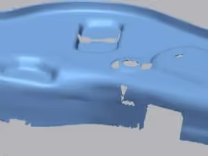
Point cloud acquired with the 3D scanner
The polygon quality and quantity adjustment can help to control the final size of the meshed model. It is also essential in terms of storage and data transfers in case you are planning to outsource further model processing.
It is essential to monitor sizes and set the axis system of the resulting model. Sometimes even changing the background can be the right decision and will save a lot of time searching for the holes in the point cloud.
Big holes sometimes look tempting to fill and approximate them, but in most cases, it is much better to leave them as is.
The most difficult to scan materials are plastics, and sometimes shiny materials like stainless steel. Quality metal parts scans are less demanding. Moreover, plastic parts shrink after the manufacturing process. But with all the years of experience, our specialists can recreate your original design intent even from deformed plastic parts scans.
It is common for us to see old worn-out machinery. So not only do we have to scan this, but rebuild – via the CAD models and compensate for the areas that have worn. Some of our Aerospace projects like this have been very interesting. So that design intent can be a very important part of this process.
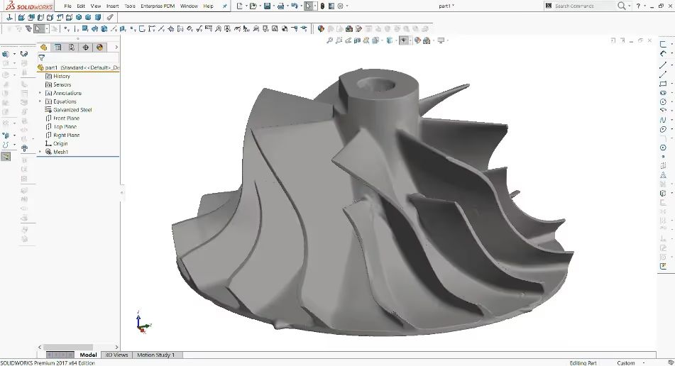
3D CAD model created from point cloud
Get a Quote now and we will do our best in delivering your CAD Perfect™ experience.
GET A QUOTE
FAQ’s
3D Scanning FAQS
Can you scan the internals of my parts?
Depending on the situation we can offer you dissecting your part for scanning purposes or use CT if applicable.
What is the minimum price for your scanning services?
For 3D scanning services our minimum order fee is $120.
How good are your 3D CT scanners?
4 to 400µm/voxel resolution
Full inspection of large size samples
Modular and micro-resolution capability
6 motion axis
Can your scanners find voids in materials?
Yes. This is one of CT scanners’ major points – to see into objects. This is the best solution for nondestructive quality control.
Do you support CT scanning?
Yes with both the DeskTom and EasyTom CT scanners. They both support metrology grade Computed Tomography (CT) inspection. This provides nondestructive, 3D Scanning of Internal and External Geometries. We use the Volume Graphics VGStudio Max high-end industrial CT software for the demanding of CT applications.
How accurate is 3D scanning?
The scanners we use are as accurate as the industry offers – from anybody at any cost. We use Faro and Artec 3D scanners, in addition to Faro CMM type arms, including the Surveyor tables. Depending on what scanner we use:
CT scanners – 4 to 400µm/voxel resolution
Artec Portable scanners high accuracy (0.03 – 0.05mm)
Artec Portable scanners high resolution (up to 0.15mm)
Our CyberGage 360 – generates highly precise full 360 degrees automated scan with accuracy NIST traceable to approximately 7 microns
The CyberGage 360 has a system repeatability of ±.005mm.
Faro Arm – Very good for most parts, fast and accurate
Turntable scanners – high accuracy, high detail, fast scanning. Great for smaller parts.
Portable handheld – may be favorable for some larger parts – if not a tripod-mounted scanner.
Long Range – these mount on a tripod, and are intended to scan buildings, plants, and other larger sized projects.
Industrial CT scanners – incredibly expensive, but they offer two main benefits – the ability to inside an object (think of a void in a solid object), and their accuracy. At this level, we are often in the ±.001” – ±.002” range, and often used in metrology scanning.
What is the Point Cloud/Mesh/3D Scan?
A point cloud is thousands if not millions of data points located in space by X, Y, Z coordinates. Images of this nature are often captured with Faro Focus or Artec scanners that specialize in large-area scanning. Most likely you obtain building and territory plans in this file format.
A polygon mesh is a set of triangles located in the same manner. These scans are obtained with Artec, Creaform, Enscan and other handheld scanners. Parts and reverse engineering device scans are usually polygon meshes.
How much does scanning services cost?
It depends on the complexity of the scanned model and material properties. As, for example, it may be much more complicated to properly scan an object with a reflective surface, than a non-reflective surface. It also depends on three main factors:
the physical size of your part
the required scanning resolution
if industrial CT or metallurgy scanning is needed
Simple quick cell phone photos are worth a thousand words to us. To know for sure you can request a quote. It is of course, free – and treated as if an NDA is already in place.
Some averages:
The typical 3D scan is somewhere around $200-400 per part.
Tomographic (CT) scanning is $600-900 per part.
Because so much of our business is Aerospace related, our scanning – and the completed CAD file HAS to be within ±.005” anywhere on that part, we never use consumer-grade scanners. The scanners we use start at $25,000 and go up to $700,000 (CT) per scanner.
At any given time, we have in excess of $ 5 million just in scanning hardware we use. In addition, a hidden factor of scanning on any system is the assembly and clean up of any scan. The rule of thumb is a 2-1 ratio. So even with our experienced scanning staff, if we spend one-hour scanning; we will then spend an additional two hours of clean up and assembly before our CAD group gets the Point Cloud file to simulate or reverse engineer.
What is the difference between 3D scanning and Scan to CAD?
3D scanning captures the physical shape of an object. Scan to CAD converts that scan data into a usable CAD model for engineering,
manufacturing, inspection, or documentation.
Can 3D scanning be used for reverse engineering?
Yes. 3D scanning is commonly used for reverse engineering when original CAD files, drawings, or design data are missing or outdated.
What file formats can be delivered from 3D scanning?
Common deliverables include point clouds, STL files, STEP files, IGES files, CATIA files, Siemens NX files, Creo files, SolidWorks files, Inventor files, inspection reports, and deviation maps.
Is 3D scanning accurate enough for manufacturing?
Yes. Professional 3D scanning can be sufficiently accurate for manufacturing, inspection, reverse engineering, and quality control when the appropriate scanning method and tolerance requirements are used. Most of the time, we are good to within ±.005” of the object.
This also allows us to ‘fix’ a problem spot. Consider a turbine with a broken blade, a worn blade, a broken edge, and more.
What is 3D scanning?
3D scanning is the process of digitally capturing the exact size, shape, and geometry of a physical object using laser, structured light, or other optical scanning technologies. The resulting point cloud or mesh can be converted into editable CAD models, engineering drawings, inspection reports, or digital twins.
What is 3D scanning used for?
Outsourced CAD services are commonly used in aerospace, defense, automotive, medical devices, industrial equipment, consumer products, energy, maritime, and manufacturing industries. Companies often outsource CAD work to increase engineering capacity, accelerate project schedules, and access specialized software expertise.
Professional 3D scanning is commonly used for:
Reverse engineering
CAD model creation
Point cloud to CAD conversion
Quality inspection
Digital twin creation
Product redesign
Legacy part digitization
Manufacturing support
Tooling verification
Technical documentation
What industries use professional 3D scanning services?
3D scanning is widely used in:
Aerospace
Defense
Automotive
Manufacturing
Industrial equipment
Medical devices
Energy
Heavy equipment
Construction
Consumer products
What is Scan-to-CAD?
Scan-to-CAD is the engineering process of converting scanned point cloud or mesh data into accurate, fully editable CAD models that can be modified, manufactured, analyzed, or documented.
Can you convert a 3D scan into a CAD model?
Yes. We convert point clouds and mesh files into fully editable CAD models using CATIA, Siemens NX, Creo, SolidWorks, Inventor, AutoCAD, and other leading engineering platforms.
What is reverse engineering with 3D scanning?
Reverse engineering combines 3D scanning with CAD engineering to recreate digital engineering data from an existing physical part when original CAD files or drawings no longer exist.
What is a point cloud?
A point cloud is a collection of millions of measured XYZ coordinate points captured by a 3D scanner. Engineers use this data to create CAD models, inspection reports, digital twins, and manufacturing documentation.
How accurate are professional 3D scanning services?
Professional metrology-grade 3D scanners typically achieve accuracies ranging from approximately 0.020 mm to 0.100 mm, depending on the scanner technology, part size, material, and project requirements.
What file formats can you deliver?
We support virtually all major engineering formats, including:
STEP
IGES
Parasolid
CATIA
Siemens NX
Creo
SolidWorks
Inventor
AutoCAD
STL
OBJ
PLY
E57
JT
DXF
DWG
Can you scan large parts and assemblies?
Yes. We perform large-scale 3D scanning for aircraft, industrial machinery, vehicles, production equipment, tooling, manufacturing fixtures, and large assemblies both on-site and in-house. CAD / CAM Services has scanned entire aircraft, 10-story buildings, and even offshore oil rigs.
What is the difference between laser scanning and structured light scanning?
Laser scanning is often preferred for larger objects and field applications, while structured light scanning typically provides exceptional accuracy for smaller precision components. The appropriate technology depends on your part size, accuracy requirements, and project goals.
What is a digital twin?
A digital twin is an accurate digital representation of a physical asset created from 3D scanning, CAD models, and engineering data. Digital twins support maintenance, modernization, simulation, lifecycle management, and predictive engineering.
Can you reverse-engineer obsolete or discontinued parts?
Yes. One of the primary applications of 3D scanning is recreating obsolete, damaged, or discontinued components when original engineering documentation is unavailable.
Can 3D scanning improve manufacturing quality?
Absolutely. Manufacturers use 3D scanning to verify part dimensions, inspect assemblies, compare manufactured parts against CAD models, validate tooling, and improve production quality through accurate inspection data.
Do you provide on-site 3D scanning services?
Yes. We perform on-site 3D scanning throughout North America using portable metrology-grade equipment. Customers may also ship parts to our engineering facilities for scanning.
How much do professional 3D scanning services cost?
Pricing depends on factors such as part size, complexity, required accuracy, travel requirements, engineering effort, and final deliverables. Small projects may cost only a few hundred dollars, while large reverse-engineering and facility-scanning projects may require more extensive engineering effort.
How long does a typical 3D scanning project take?
Many small scanning projects can be completed within a few business days. Larger reverse engineering, aerospace, industrial, or facility scanning projects typically require additional time depending on complexity and deliverables.
Can you create manufacturing drawings from scanned parts?
Yes. In addition to creating CAD models, we produce complete manufacturing drawings, GD&T documentation, Model-Based Definition (MBD), Product Manufacturing Information (PMI), and Technical Data Packages (TDPs).
Why should I outsource 3D scanning instead of purchasing equipment?
Professional 3D scanning systems require a significant investment in equipment, software, training, and ongoing calibration. Outsourcing allows organizations to access experienced engineers, advanced scanning technology, and high-quality deliverables without the cost of owning and maintaining specialized equipment.
When should I use laser scanning?
Laser scanning is the preferred choice when capturing large objects, complex assemblies, or industrial environments where speed, range, and accuracy are essential. It works well for aircraft, vehicles, factory equipment, buildings, production lines, piping systems, tooling, and large manufactured components.
Laser scanners collect millions of measurement points while maintaining excellent accuracy over both short and long distances. They are commonly used for reverse engineering, quality inspection, as-built documentation, digital twin creation, modernization projects, and point cloud generation.
Laser scanning is especially valuable when you need to:
Scan large or complex parts
Capture existing conditions for engineering projects
Reverse engineer obsolete components
Create accurate CAD models
Verify manufactured parts against CAD
Document industrial facilities
Support aircraft modernization programs
Produce digital twins
For many industrial applications, laser scanning offers the best balance of accuracy, speed, portability, and scalability.
When should I use structured light scanning?
Structured light scanning is ideal when maximum accuracy and fine detail are required on small to medium-sized parts. Instead of using a laser, the scanner projects a series of light patterns onto the object and measures how those patterns distort to create an extremely detailed 3D model.
This technology is commonly used for precision manufacturing, tooling, molds, medical devices, consumer products, turbine blades, injection-molded parts, castings, and highly detailed mechanical components.
Structured light scanning is recommended when you need to:
Capture intricate surface details
Inspect precision-machined parts
Reverse engineer complex geometry
Verify tight manufacturing tolerances
Scan delicate or highly detailed components
Create high-resolution CAD models
For small precision components, structured light scanning often delivers exceptional detail and repeatability.
When should I use industrial CT scanning?
Industrial CT (Computed Tomography) scanning should be used when you need to inspect or reverse engineer both the external and internal geometry of a part without cutting it open or damaging it.
Unlike laser or structured light scanners, CT scanners capture hidden internal features such as cooling passages, internal cavities, wall thicknesses, porosity, cracks, and assembled components. This makes CT scanning invaluable for complex castings, injection-molded parts, additive-manufactured components, medical devices, electronics, and aerospace hardware.
Industrial CT scanning is ideal for:
Internal feature inspection
Failure analysis
Non-destructive testing
Reverse engineering complex assemblies
Wall thickness analysis
Porosity detection
Casting inspection
Mold validation
Quality control
Product development
When internal geometry is just as important as external dimensions, industrial CT scanning is often the most effective solution.
When do I need photogrammetry?
Photogrammetry is the preferred technology for capturing extremely large objects or environments using high-resolution photographs. Specialized software combines hundreds or thousands of overlapping images to generate an accurate 3D model or point cloud.
Photogrammetry is particularly useful for projects involving buildings, bridges, ships, aircraft exteriors, mining operations, construction sites, historical structures, and large industrial facilities where traditional scanning methods may be less practical.
Typical applications include:
Building documentation
Infrastructure surveys
Construction progress monitoring
Historic preservation
Mining operations
Large facility documentation
Civil engineering projects
Terrain mapping
Large aircraft documentation
Outdoor industrial assets
Photogrammetry is often combined with laser scanning to produce comprehensive digital models that balance engineering accuracy with efficient coverage of large areas.
When should I create a digital twin?
A digital twin should be created whenever an organization needs a continuously accurate digital representation of a physical asset to support engineering, operations, maintenance, or modernization throughout its lifecycle.
Digital twins are developed using 3D scanning, CAD modeling, engineering documentation, inspection data, and operational information to create a comprehensive digital model that mirrors the real-world asset.
Organizations commonly create digital twins for:
Aircraft modernization
Manufacturing facilities
Industrial machinery
Energy infrastructure
Production lines
Buildings and campuses
Oil and gas facilities
Transportation assets
Military equipment
Long-term asset management
A digital twin enables engineers to perform design updates, simulate changes, plan maintenance, monitor asset conditions, improve manufacturing processes, and preserve engineering knowledge without relying solely on physical equipment. For organizations managing complex or aging assets, digital twins reduce risk, improve decision-making, and support long-term operational efficiency.
Why choose CAD/CAM Services for 3D scanning?
Since 1988, CAD/CAM Services has provided professional engineering support for reverse engineering, CAD modeling, point cloud-to-CAD conversion, digital modernization, and legacy data conversion. Our experienced engineering team supports aerospace, defense, manufacturing, industrial equipment, and government organizations with high-accuracy deliverables and rapid turnaround times.
Reverse Engineering FAQs
What is the quality of reverse-engineered parts?
We can provide ±.005” aerospace quality for every model. CT scanned parts can have even higher precision up to ±.001”.
What do you guys need to provide me with accurate pricing?
We need to know whether you need your parts to be scanned by us. Or many times we can work with 3D scans provided by third-party companies. The quality of the scan is everything in our business. Anyway, we strongly advise you to use us for both the scanning and the CAD conversion aspects. That way, we can control the quality. Sometimes we receive poor quality scans which make it impossible to create truly Cad Perfect™ models for you. By all means, send us a couple of even cell phone photos, and the rough size of the object. Most of the time, this will provide us enough information to provide a real bid.
The price depends on the part complexity, size, as well as the target file parametres. We need to know whether you need full parametric models, and your desired accuracy. If you tell us the purpose of reverse-engineered models, we can often provide you with possible solutions. The target CAD software may change the price as well. This includes sophisticated Workstation add-on products such as Composites, Catia electrical wiring, mold design, and others.
What is the average price for Reverse Engineering?
It all depends on the part’s complexity, size and structure.
What is reverse engineering?
Reverse engineering is the process of analyzing an existing physical object, product, component, assembly, or system to understand its design, dimensions, materials, and functionality so it can be recreated, modified, documented, or manufactured again.
In the CAD and engineering world, reverse engineering typically involves converting a physical part into accurate 3D CAD models, 2D drawings, and engineering documentation.
We often: 1) Capture Existing Data by 3D scanning, 2) create a Digital model, often called a Point Cloud, 3) build a 3D model, and 4) produce the required engineering documentation.
How accurate is reverse engineering?
Typical Accuracy Ranges
Hand Measurements (Calipers, Micrometers) ±0.001" to ±0.010"
Structured Light Scanning ±0.001" to ±0.005"
Laser Scanning ±0.002" to ±0.010"
Photogrammetry ±0.010" to ±0.100"+
CMM Measurement ±0.0001" to ±0.001"
Hybrid Scan + CMM Validation ±0.0005" to ±0.002"
For aerospace, medical, and precision manufacturing applications, a combination of 3D scanning and CMM inspection is often used to achieve the highest accuracy.
Also, there can be two parts to this answer: 1) The accuracy of the scanner, and then 2) if we are going all the way to an editable feature-rich CAD file. If we are going all the way to the CAD file, we are within ±.005” of any Point Cloud data.
What is the difference between 3D scanning and reverse engineering?
Many people use the terms 3D scanning and reverse engineering interchangeably, but they are not the same thing.
3D scanning is the process of capturing an object's geometry. Reverse engineering is the process of converting that captured data into usable engineering information, such as CAD models, drawings, and manufacturing documentation.
Simple Explanation
Think of it this way:
3D Scanning = Data Collection = a picture of 1,000,000 dots in 3D space
A 3D scanner captures the shape of an object. Reverse engineering transforms that shape into an intelligent, editable CAD model that engineers and manufacturers can use.
Can you reverse engineer a part without drawings?
Yes. In fact, most reverse engineering projects begin with no drawings, CAD files, or engineering documentation at all.
Engineers can reverse engineer a part using the physical component itself, measurements, 3D scanning, inspection equipment, and engineering analysis to recreate the original design.
Can you reverse engineer obsolete parts?
Yes. Reverse engineering obsolete parts is one of the most common reasons organizations pursue reverse engineering services.
When original manufacturers no longer support a component—or when CAD files, drawings, tooling, and engineering records have been lost—reverse engineering can recreate the engineering data needed to manufacture replacement parts and extend the life of critical equipment.
Why Obsolete Parts Need Reverse Engineering
Organizations often face situations where:
The original manufacturer is no longer in business.
Replacement parts are unavailable.
CAD files and drawings have been lost.
Legacy equipment remains operational and critical.
Lead times for replacement equipment are too long.
Modern equivalents are incompatible with existing systems.
Rather than replacing an entire machine, reverse engineering allows companies to reproduce the specific component that has become unavailable.
How much does reverse engineering cost?
Typical Reverse Engineering Cost Ranges
Simple Part $500–$2,500
Mechanical Assembly $2,000–$15,000
Tool & Die Reverse Engineering $5,000–$50,000+
Point Cloud to CAD $1,000–$100,000+
Aircraft & Defense Projects Custom Quote
Factors That Influence Cost
Part Complexity
A simple machined block with a few holes may require only a few hours of engineering effort, while a complex casting with freeform surfaces can require significantly more modeling time.
Part Size
Larger parts generally require:
More scanning time
More measurement data
More CAD reconstruction effort
Can reverse engineering create a Digital Twin?
Yes. Reverse engineering is often the first step in creating a Digital Twin, especially when original CAD models, engineering drawings, or product data are unavailable.
A Digital Twin is a digital representation of a physical asset that accurately reflects its geometry, structure, and, in many cases, its operational behavior. Reverse engineering provides the engineering data needed to build that digital representation.
How Reverse Engineering Supports Digital Twin Creation
When an organization has a legacy asset with limited or missing documentation, engineers can:
Capture the physical asset using 3D scanning and measurement technologies.
Create accurate CAD models through reverse engineering.
Generate engineering documentation and metadata.
Integrate the resulting models into simulation, PLM, BIM, IoT, or asset management systems.
Establish a Digital Twin that can be updated throughout the asset's lifecycle.
Can you create manufacturing drawings from a scanned part?
Yes. Manufacturing drawings can be created from a scanned part, but the process involves more than simply scanning the component.
A 3D scan captures the physical geometry of the part, while engineers use reverse engineering techniques to create an accurate CAD model and generate production-ready manufacturing drawings.
The final drawing package may include:
Orthographic views
Dimensions
Tolerances
GD&T
Material specifications
Surface finish requirements
Notes and callouts
Bill of Materials (BOM)
Do you support aerospace and defense reverse engineering?
Yes. Aerospace and defense reverse engineering is a specialized engineering service used to recreate, modernize, and support legacy aircraft, military systems, ground support equipment, tooling, and mission-critical components when original engineering data is unavailable or obsolete.
Organizations throughout the aerospace and defense industries use reverse engineering to maintain operational readiness, extend service life, and create modern digital engineering assets for aging platforms.
Why Choose CAD/CAM Services?
Reverse engineering specialists since 1988
Millions of CAD models completed
100+ engineers and drafters
CATIA, NX, Creo, SolidWorks, and Inventor experts
Aerospace, defense, industrial, and government experience
U.S.-based engineering team
ITAR-capable projects
Model-Based Definition (MBD) expertise
Digital Twin and engineering modernization support
Can You Reverse Engineer My Part?
In most cases, yes. CAD/CAM Services can reverse engineer nearly any physical component, assembly, tool, mold, aircraft structure, industrial machine component, or legacy product. We work from physical parts, point clouds, STL files, photographs, legacy drawings, PDF documents, scanned blueprints, and existing CAD data.
Whether you need a simple replacement bracket or a complete aircraft assembly recreated in CATIA, Siemens NX, Creo, SolidWorks, or Inventor, our engineering team can develop the CAD models, manufacturing drawings, and engineering documentation required for production, maintenance, modernization, or Digital Twin initiatives.
What Information Do You Need to Start a Reverse Engineering Project?
The ideal starting point is a physical part or assembly. However, we can also work from:
Existing CAD files
STL or mesh data
Point cloud data
Legacy engineering drawings
PDF documents
Photographs
Inspection reports
Technical manuals
Tooling and molds
If multiple samples are available, they can help identify wear, manufacturing variation, and original design intent.
How Long Does Reverse Engineering Take?
Project duration depends primarily on part size, complexity, accuracy requirements, and deliverables.
Typical turnaround times include:
Project Type
Typical Schedule
Simple Mechanical Part
1–5 Days
Complex Component
1–3 Weeks
Multi-Part Assembly
2–6 Weeks
Industrial Equipment
2–8 Weeks
Aircraft Structures
4–12 Weeks
Enterprise Modernization Programs
Multi-Month
Rush services are available for critical manufacturing, maintenance, and defense requirements.
What Deliverables Will I Receive?
Depending on project requirements, deliverables may include:
Native CATIA CAD Models
Siemens NX Models
Creo Models
SolidWorks Models
Autodesk Inventor Models
STEP Files
IGES Files
Parasolid Files
Manufacturing Drawings
GD&T Documentation
Product Manufacturing Information (PMI)
Model-Based Definition (MBD)
Technical Data Packages (TDP)
Point Cloud Data
Digital Twin Models
Inspection Reports
What Industries Use Reverse Engineering?
Reverse engineering is commonly used in:
Aerospace
Defense
Industrial Equipment
Manufacturing
Energy
Automotive
Shipbuilding
Transportation
Medical Devices
Government Agencies
Organizations rely on reverse engineering to support modernization, sustainment, replacement parts, Digital Twin development, and engineering data recovery initiatives.
Why Do Companies Reverse Engineer Obsolete Parts?
Many organizations operate equipment that remains mission-critical long after OEM support has ended.
Common reasons include:
Lost CAD files
Missing engineering drawings
Discontinued replacement parts
Legacy military systems
Aging manufacturing equipment
Long lead times for replacement assets
Reverse engineering allows companies to recreate accurate CAD models and manufacturing documentation so replacement components can be manufactured and supported for years to come.
Can Reverse Engineering Support Digital Twin Initiatives?
Yes. Reverse engineering is often the first step in creating a Digital Twin of existing equipment, facilities, tooling, aircraft, vehicles, or industrial assets.
By creating accurate CAD models and engineering documentation from physical assets, organizations establish the digital foundation required for:
Digital Twin programs
Digital Thread initiatives
Lifecycle management
Predictive maintenance
Asset management
Engineering data modernization
Why Choose CAD/CAM Services for Reverse Engineering?
Since 1988, CAD/CAM Services has focused exclusively on creating CAD data and engineering documentation for manufacturers, aerospace companies, defense contractors, government organizations, and industrial clients.
Our team of over 100 engineers and CAD specialists has completed millions of CAD models and supports CATIA, Siemens NX, Creo, SolidWorks, Inventor, and numerous neutral CAD formats.
Whether the project involves a single replacement part or a multi-year engineering modernization initiative, we provide the expertise necessary to convert physical assets into accurate digital engineering data.




.webp)
.avif)
.avif)
.avif)

.avif)
.avif)
.avif)