Case Studies
CAD / CAM Services has established a distinguished clientele and a reputation in the international marketplace for its top of the line CAD Conversion & Modeling services. In this case study, we follow the technical process adopted by our competent team for a flow calculation project.
The Task
Our client, a high-end hydroelectric power plant, was faced with the challenge of designing an optimal fluid transportation channel. Their plant was quite a complex structure that lacked efficiency. It was composed of several components and phases through which the high-velocity water passed through before generating electricity.
The company was following a 60-year-old design that only had access to outdated 2D drawings. They lacked the technical prowess to develop a CAD model from those drawings and could not carry out a flow calculation for their pipe channel. For this project, they consulted the reliable team of CAD / CAM Services, who solved their problem efficiently and professionally.
CAD / CAM Services received various 2D drawing orientations of the flow channels. These depicted how they were to look if viewed from a specific angle. From this initial data, our team had to build a 3D model and then carry out the required flow calculation. The 3D model would enable the client’s engineers to visualize and maximize their flow rate, optimizing it to their own power plant.
The Challenge
The task was simple enough and well-defined, but still posed a clear challenge to our team. The tricky part was the interpretation of the 60-year-old drawings of the piping network, which are never reliable enough to be copied as is. A current set of “as builts” had to be created first.
Over time, the drawings sheets wear out and become yellow, the dimensions distort, and the ink rubs off in most places, making it quite a task to build an accurate 3D model.

The Solution: A Realistic Flow Simulation
To carry out a flow calculation, the main pre-requisite is a model of the flow channel. The only information available to us, was in the form of 2D sketches.
Our team pondered over this problem and brainstormed over which CAD platform to use. The software had to be good enough to create the 3D model, carry out a good simulation, and be compliant with mainstream platforms too. SolidWorks became the preferred option and was finalized as it met all the aforementioned requirements and is a world-renowned software for CAD.
The first challenge our skilled CAD experts were faced with was the conversion of the 2D sketches to vector form. For this, we used our propriety software to prepare raster images of the sketches, which shed some light on the missing parts of the original design. The next step was to convert these raster images to vector form, which was performed using SolidWorks. Contours lost over time were fixed and a clear, editable vector image was developed.

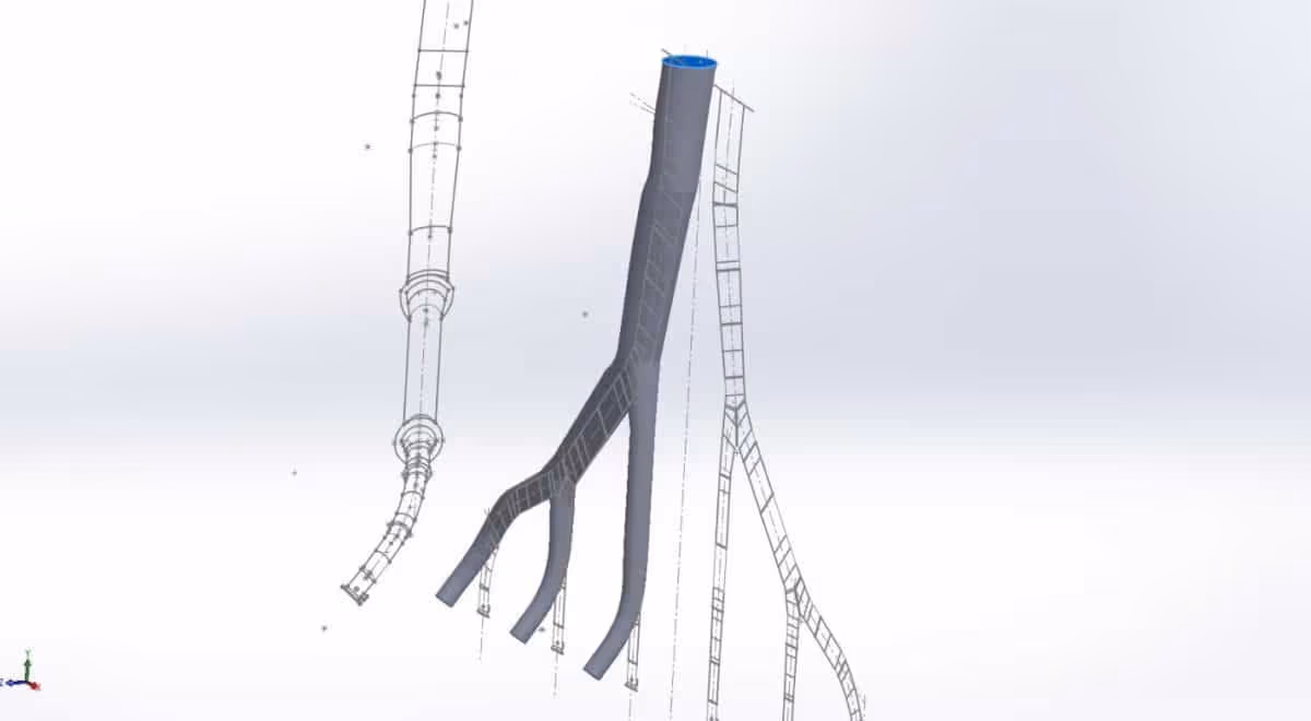
Using these, CAD / CAM Services then created a 3D model that superimposed multiple views onto each other and added thickness to it, depicting the exact flow path.
The next step in the flow calculation process was to design the analysis. SolidWorks Simulation was used due to its accuracy and standardization. Like any flow calculation, the first step was to define the inputs and boundary conditions, which were assigned to the inlet and outlet cross-sections of the 3D model.
Then various parameters such as velocity, pressure, viscosity etc. were fed into the system in order to make the simulation as realistic as possible. All useful properties had been measured precisely by our clients and communicated to us beforehand.
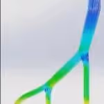
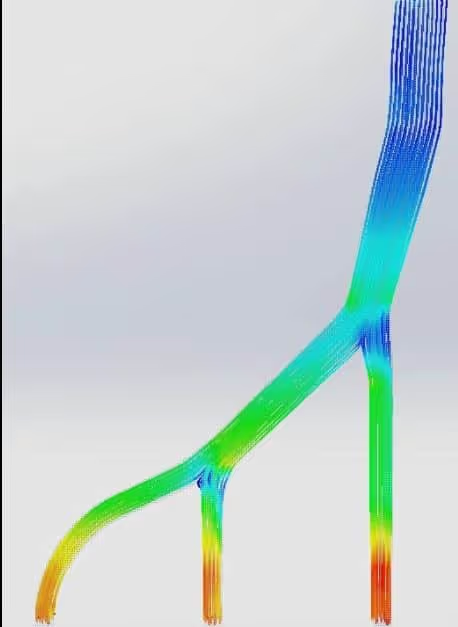
Finally, our state of the art computers were used to carry out the flow simulation. The end results were obtained and converted to a video which showed the change in fluid velocity as it passed through the channel. The calculations showed the expected fluid velocities at each point in the channel, allowing engineers to analyze their design in detail and make any changes as desired.
Deliverable
The deliverables of this project included the SolidWorks files: the raster images, vector images, and simulation files. All of these were editable so that our client can re-perform this flow calculation with new parameters any time they want.
Accompanying these were the flow simulation results that summarized the parameters used and showed the results.

Added Value
This project added considerable value not only to the current design the power plant adopted but also to the design process. Using our flow calculations, the client was able to retrofit new turbines in their channels that suited the flow conditions better and reported an appreciable 12% increase in power generation.
Our client was immensely impressed and satisfied by our work and praised the accuracy of the simulation. Not only was this an exact model of their visualized ideas but also portrayed its working in a real-life situation, speaking volumes about our quality of service and professionalism.
If you have 2D engineering drawings that you want to run as 3D simulations, call CAD / CAM Services @ 1-800-938-SCAN.
Let our team of experts help you with your upcoming 3D modeling project.