CAD Modeling of an F‑16 from 3D Scan to Simulation-Ready

1. Overview
This case study describes how we helped a defense customer turn a dense point cloud into a usable surface model. This model was a CAD surface for an F‑16 that could feed straight into simulation. This involved data ingestion, data integration, and managing data from high‑volume data sources. We also had to apply precise 3D modeling techniques with a glance toward machine learning possibilities for smarter workflows.
2. Customer’s Real‑World Challenges
- The client faced data overload. They had a dense point cloud – billions of triangles from a 3D scan that reached the level of massive data feeds.
- The initial file size was 25 GB, and the raw data posed bottlenecks and risked overwhelming their systems. They needed data management strategies to toggle the sheer volume of data into something manageable.
- They needed a surface model accurate to ±.004”. They also required a CAD surface that represented control surfaces, wing-body junctions, and fuselage details.
- Handling point clouds without losing accuracy demanded data ingestion, data integration, and robust data security.
- The client wanted to extract meaningful insights from this mass of historical 3D data. This would enable informed decisions about geometry, composites, and downstream simulation.
3. Our Approach: From Raw Data to CAD Surface
Step 1: Data Ingestion and Early Filtering
We ingested the raw point cloud, which contained tens of millions of data points across the entire aircraft surface. Using robust registration protocols, we segmented the data into manageable zones. This includes wing panels, fuselage sections, and control surfaces. In so doing, we established a clean coordinate frame aligned to aerospace datums.
Step 2: Mesh Generation and Cleanup
The next step was to mesh the point cloud into polygonal surfaces and fill the gaps. After that, we removed noise and smoothed overlapping scan artifacts. Doing this ensured the geometry was structurally coherent and ready for CAD surface fitting.
Step 3: Surface Reconstruction and CAD Translation
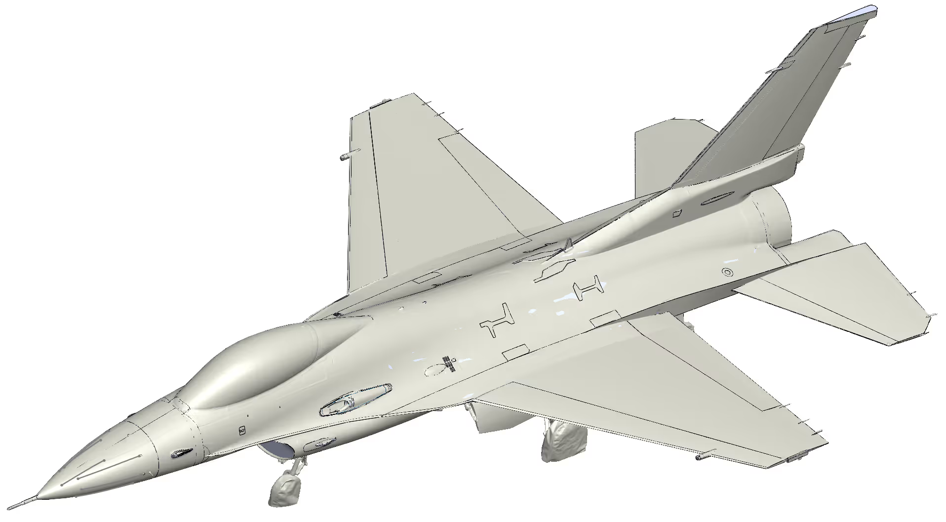
Once cleaned, we performed surface reconstruction, converting the point clouds to NURBS and spline surfaces in CATIA and NX. This CAD translation created the surface model with ±.004” accuracy. This allowed us to represent the control surfaces as clear, editable local geometry.
Step 4: Quality Verification
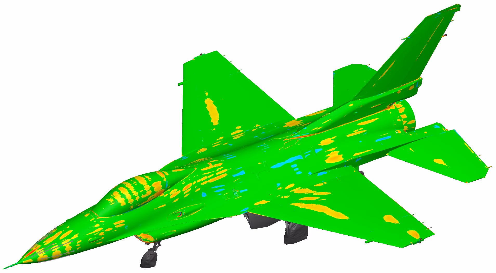
Finally, we conducted point-to-surface comparisons to the original scan to confirm fidelity. We used advanced surface-fitting techniques, including NURBS and high‑order B‑splines. These methods allowed us to reconstruct smooth, continuous surfaces while preserving critical features and curvature coherent junction. Our verification process used data analytics to validate tolerances.
4. Results and Insights
The final model was ready for simulation, with real‑world readiness and precision. We delivered the product in less than eight weeks. This saved the client at least six months in ramp‑up time.
The clean 3D modeling output gave engineering teams confidence to move into Ansys and structural work without hesitation. Our data management strategies and phased data ingestion kept massive data feeds from overwhelming systems. We also took care to maintain data security at every step.
Finally, we preserved the scanned detail in a structured, repeatable workflow capable of handling various data types. These spanned from legacy historical data to modern LIDAR scans. We also created an F-16 canopy from a scanned PC image to an actual CATIA file and now use this in one of our videos.