How to Upgrade Your Reverse Engineering with Deviation Analysis
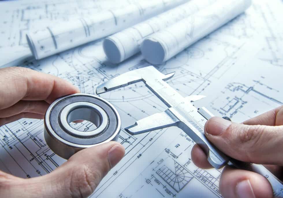
Reverse engineering a part isn’t always as easy as using a tape measure and re-drawing it on CAD. If your part has small features or curves that are tough to map, you might feel stuck. This is where deviation analysis can really shine. In this quick guide, we’ll explain what deviation analysis is, and how it can help.
The Purpose of Reverse Engineering
The first point to discuss is why you might reverse engineer a part in the first place. As you probably know, reverse engineering is the process of taking a manufactured part, and creating a 2D drawing package for it.
Typically, people will need to reverse engineer a part if the original supplier didn’t provide drawings, a very old part needs to be replaced, or there was no original documentation for a part. There are so many examples where a machinist will quickly rig together a part and install it to fix an immediate problem without creating drawings. This isn’t a problem, until the original part breaks or the machine needs to upgrade, forcing an update on that part.
A quick and common way to reverse engineer a part is to 3D scan it, create a 3D model, then cut 2D drawings from that model. But, how are you supposed to know if the 3D scan was good? This is where deviation analysis comes in.
What Is Deviation Analysis?
Deviation analysis is a type of troubleshooting that compares two data sets. In the world of manufacturing, it can refer to a lot of things. It might be comparing actual throughput to theoretical throughput, comparing yields from different machines, or looking at machine degradation over its lifetime.
In engineering, this concept can be used as part of reverse engineering. In this case, you’ll be comparing the scanned data to either a 3D CAD model, or other scan data.
All About CAD Deviation Analysis
When you perform deviation analysis on CAD, it is described as either Computer-Aided Verification (CAV) or Computer-Aided Inspection (CAI). In either of these cases, the result is the same. You’ll be using a CAD program to automate the deviation analysis process.
An Example of Deviation Analysis in Reverse Engineering
Let’s look at an example. Imagine you have to reverse engineer a protective metal shroud for your buffing machine. The original shroud was a quick manufacturing project that wasn’t documented, so you don’t have 2D drawings to make a new one.
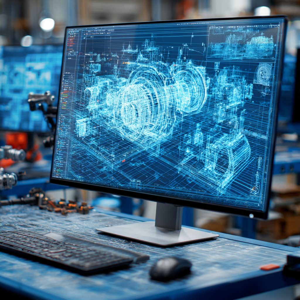
You start out by 3D scanning the shroud and getting a full point cloud. This is a collection of points that outline the part. You’ll have to process these points and create the solid part, which will become a 3D model of the shroud.
Once you have a 3D-scanned file and it’s been processed, then you can run a deviation analysis. This will highlight differences in your shroud against what the shape should look like. It will show you areas where the scan wasn’t perfect, or parts where there was deformation on the actual object.
Doing this process will raise your confidence in every 3D scan you take. It means that you can create parts that are closer to the original part that you’re reverse engineering. This translates to a lot of money and time saved across the board.
Conclusion
Just like that, you learned how to implement deviation analysis to make your reverse engineering process even better. Use these tips to start making progress, and reach out to our reverse engineering experts at CAD/CAM Services. We can fully reverse engineer your parts, including the 3D scanning process and deviation analysis. Get a free quote today.
Recent Posts

Tips for Picking the Perfect 3D CAD Viewer for Your Needs
This guide will teach you about 3D CAD viewers and outline considerations to make before picking the right one. We review 5 options and pick a clear winner.
In this guide, you’ll learn how CAD/CAM Services can save you time and money during each digitization project. Digitization can make manufacturing faster than ever before.
How to Build an Aircraft Model by Converting 3D-Scanned STL Files into Functional 3D STEP Files
This in-depth guide will teach engineers how to use 3D-scanned aircraft files and transform them into manufacturable 3D STEP files with fewer mistakes.