How CATIA 2D to 3D Conversion is Done
As with most three-dimensional design software, CATIA begins with a sketch, which is then expanded into a 3D model. However, many designs already exist as two-dimensional drawing files (mainly .dwg files), so redesigning these can be hugely time-consuming and impractical.
This can be especially problematic with intricate designs, which would take significant time to sketch again. Thankfully in CATIA, there are a couple of methods to import 2D geometry, which can then be edited accordingly into a 3D model.
The initial stage of all of the methods begins with creating a CATDrawing file, then imported into a part file, the CATIA’s main 3D modeling section. This allows for the design’s editing, ensuring that all minor details have been included accurately, as these can be easily lost in translation.
The simplest way to achieve this is to drag and drop the file directly into CATIA, which prompts the CATDrawing window to load. Then copying the geometry, opening a part file, and pasting it directly onto whichever plane.
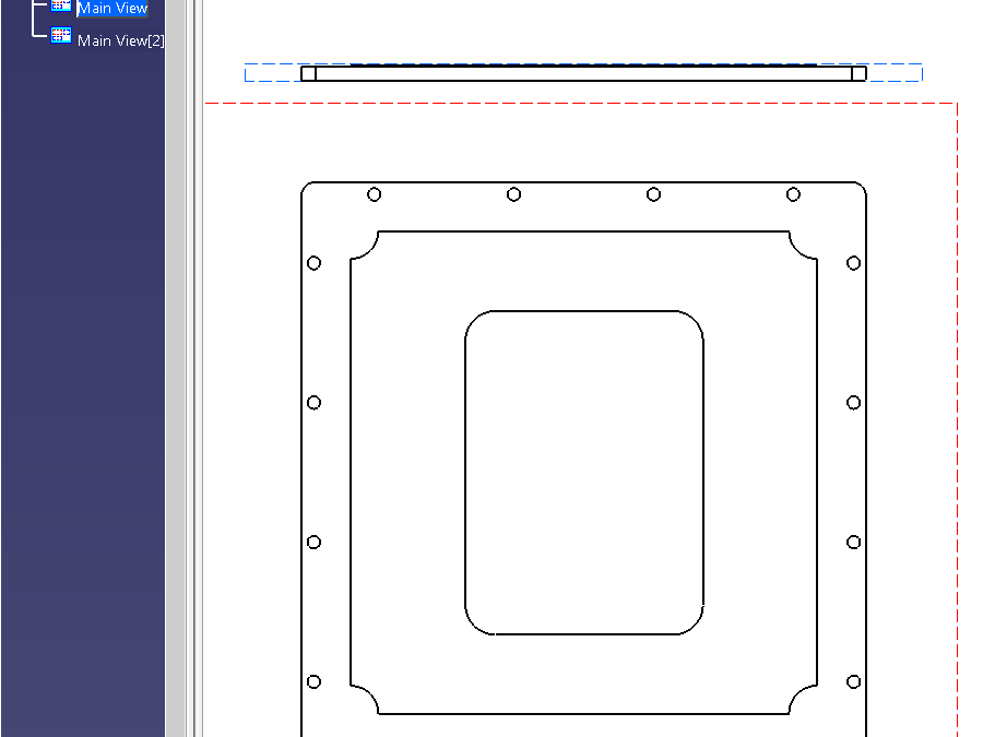
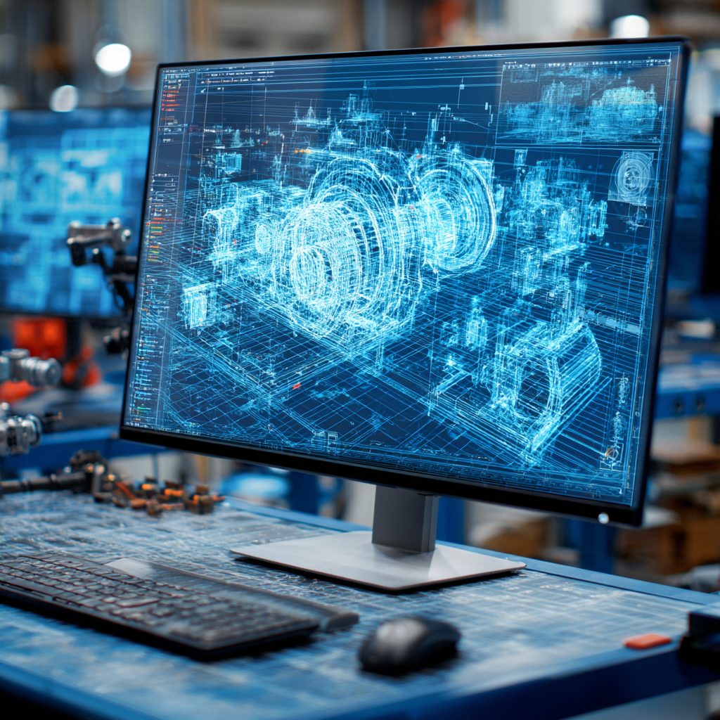
Geometry Copied into the Part File
Effectively now the geometry is the same as a newly drawn sketch, and the usual 3D tools can be used to create the desired shape. However, this method is limited in its scope of application to simple standard geometry, as only one sketch view can be imported this way.
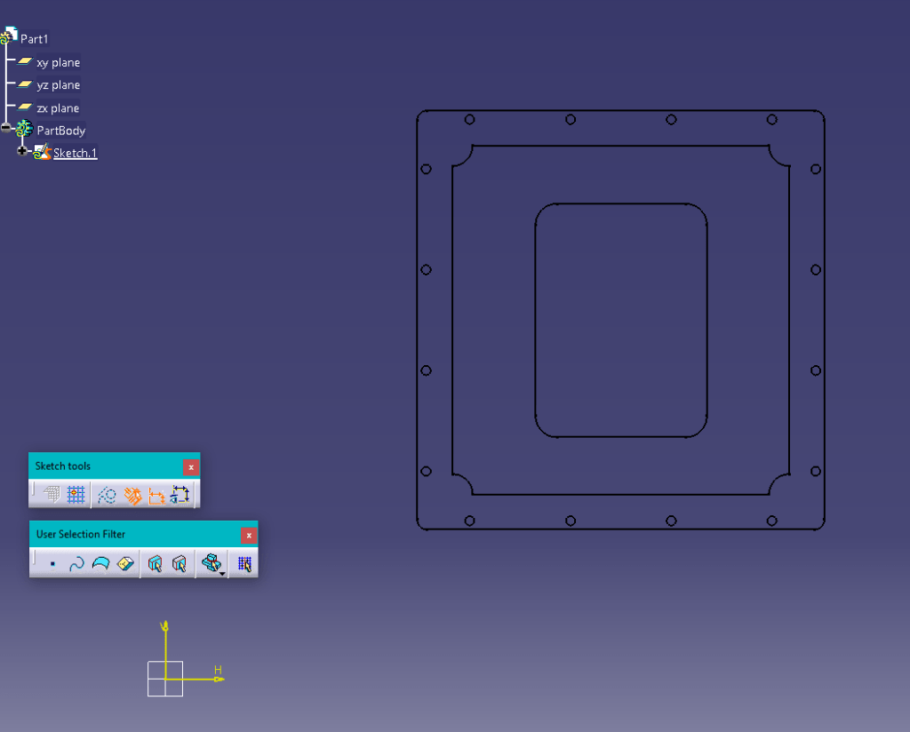
In terms of plane alignment, CATIA’s transformation tools are similar to those of SolidWorks, especially when using the ‘Align Views Using Elements’ tool. Using this, you select the geometric entities you want to align, and the views are moved accordingly.
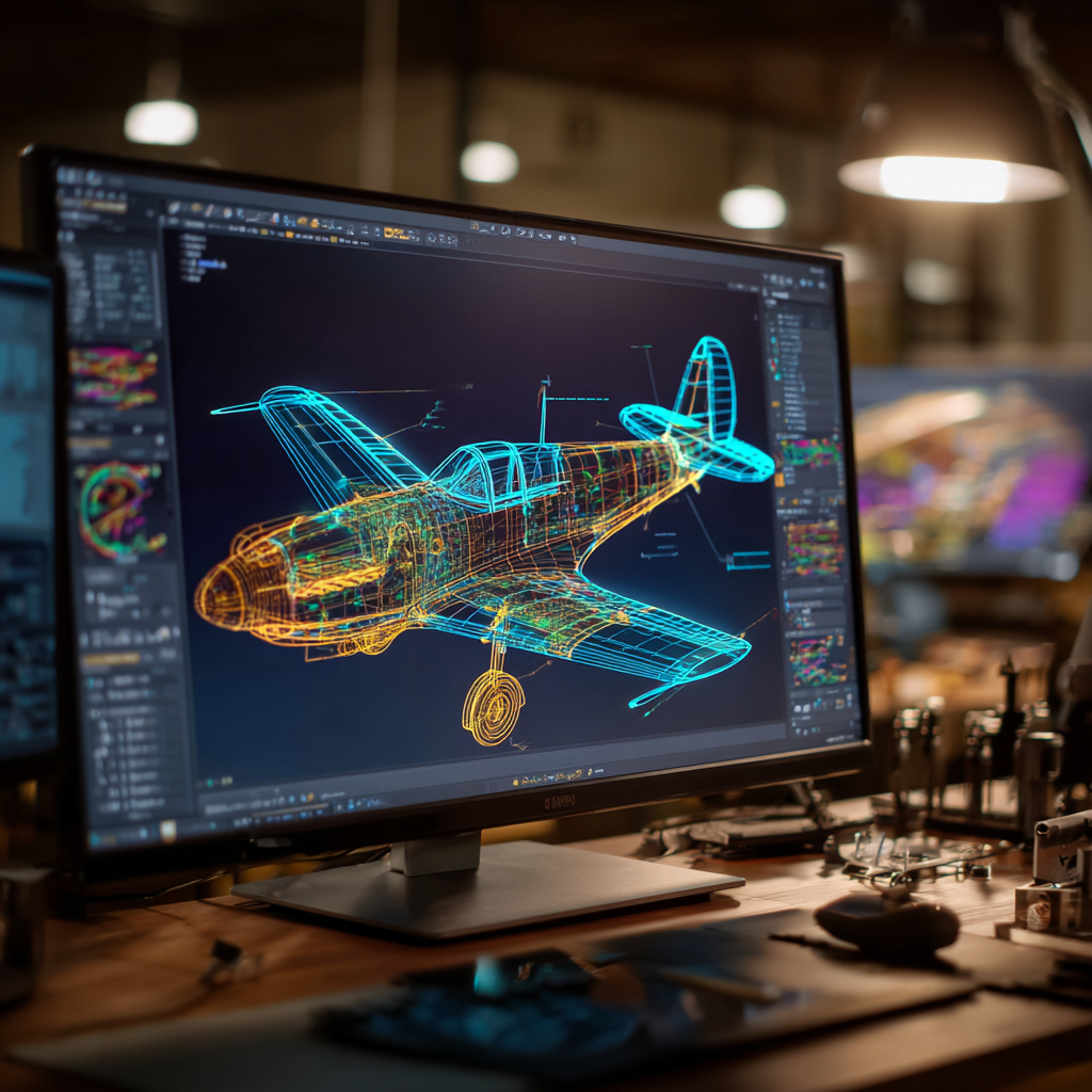
Part Views Aligned
Another method to import a 2D sketch is from the file drop-down menu, where individual files should appear, clicking on the file opens it as a .CATDrawing. The same process as above can be followed, where the geometry is simply copied and pasted into a part file.
There is another method for more detailed geometries, which entails more steps to accommodate the additional complexity. This includes a few specific actions depending on the file type.
For .DXF files, you must first open a CATDrawing file, then Tools> Import from File, which opens the file selection dialog box. You can select to browse specific file types using the bottom dropdown menu, making it easier to sort through congested folders.
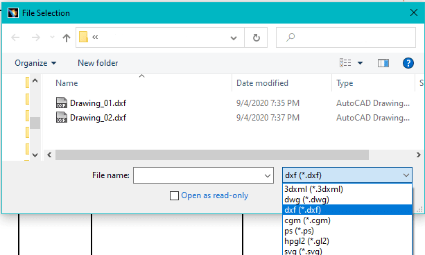
File Selection Dialog Box
There are two methods for .DWG files, the first being the same as above. The alternative way is simply from the home page, file> open, which also opens the file selection dialog box, making both of these methods largely the same. The same dialog box is used, albeit accessed differently.
There are a couple of intricacies worth noting. In import mode, a .CATDrawing is created with all the original DXF/DWG file geometry, whereas in insertion mode, the geometry is created in the current drawing.
Where multiple views of the same product exist as individual drawings, they can be imported into one file and then aligned. This can be achieved using the aforementioned ‘Align Views Using Elements’ to relate geometry to each other.
Converting 2D drawings into full 3D models is not the most intuitive with CATIA, as there is no specific methodology to achieve this; however, it can be completed. There are a few methods to choose from, each with their limitations, which can be very restrictive if not carefully considered.
These conversions are difficult to achieve accurately, with many potential pitfalls for the less experienced. Therefore, if you would like a professional service with genuine engineering design expertise, get in touch with CAD/CAM Services. By coming to us directly, we can guarantee the best service, so don’t hesitate to get your order in!
Recent Posts

Tips for Picking the Perfect 3D CAD Viewer for Your Needs
This guide will teach you about 3D CAD viewers and outline considerations to make before picking the right one. We review 5 options and pick a clear winner.
In this guide, you’ll learn how CAD/CAM Services can save you time and money during each digitization project. Digitization can make manufacturing faster than ever before.
How to Build an Aircraft Model by Converting 3D-Scanned STL Files into Functional 3D STEP Files
This in-depth guide will teach engineers how to use 3D-scanned aircraft files and transform them into manufacturable 3D STEP files with fewer mistakes.