Beginner’s Guide to Modeling in CATIA V5
CATIA V5 is one of the older 3D CAD modeling software, and a lot of people still use it today. Whether you’re an engineering manager or new to a team that uses CATIA as their preferred modeling software, you came to the right place.
In this guide, we’ll give you an introduction to CATIA V5. This beginner guide will walk through the essentials of modeling in CATIA V5. We’ll answer your questions and give you a nice shortcut at the end of the guide.
Understanding the CATIA V5 Interface
Before getting too far, let’s talk about the interface you’ll see on CATIA V5. Create a new drawing and your screen will show the following:
The top of your screen will have a ribbon bar with helpful tools. Along the bottom and side of your screen, you should notice two separate toolbars. On the top-left, there’s a specification tree.
You’ll also see a grid with your coordinate system. As you move around your mouse, you’ll see it move on your screen.
Specification Tree
The top-left specification tree gives you a lot of helpful information about your part. It essentially tells the history of your part. If you create a pad and hole in your part (more on these features later), then they will both appear on the specification tree.
It’s important to mention that the tree is linear. As you add new features, they will show up sequentially on the tree. Each feature will also have a number next to it — this also refers to the sequence in which you added parts.
If you make four Hole features in a row, then they will be listed as Hole 1, Hole 2, and so on. Under each hole command will be the referenced sketch.
You can expand and collapse the specification tree by hitting the plus or minus symbols throughout the tree.
All of your solid parts are going to be stored under “PartBody”, so you can hit the plus symbol to see all of the added features.
Some Mouse Commands
When doing modeling on CAD, the mouse is very important. One hand is almost always on the mouse while drawing.
Pressing and holding the middle mouse button while moving the mouse will allow you to pan.
You can rotate by pressing the middle mouse button and the left mouse button while moving your mouse.
Zooming is done by holding the middle mouse button and clicking the left or right mouse buttons.
Using the Sketcher Module
When you open a sketch, you’ll get a separate sketcher workbench. This is a module filled with useful tools. Whenever you open sketcher on CATIA V5, you have to pick which plane you want to sketch on.
To enter the sketcher, you can either click the Sketcher icon or you can select Start, then Mechanical Design, then Sketcher.
Once you select it, then the following toolbars will pop up:
Profile Toolbar
The profile toolbar allows you to make different geometries. You can make a circle, line, or rectangle, or you can make more complicated shapes with splines and profiles.
You can’t draw anything until you pick the tool from your profile toolbar.
Before picking a tool, think about the easiest way to make the thing you want to sketch. If you’re drawing a cylinder, then you should use a circle command. Think about the part in 2D and imagine making it with the simplest parts. This is how you should sketch a part.
Constraint Toolbar
Constraints will limit the travel and location of things that you draw. With 2D sketches, your constraint toolbar will ensure that certain features are parallel and don’t change as your drawing grows.
You can also add dimensional and angular constraints with this toolbar.
Beginners tend to have issues with constraints, so it’s okay if it’s confusing to you still. Enough practice will clear things up, or you could ask a CAD professional for help.
Operation Toolbar
The operational toolbar pops up once you create a profile. This toolbar lets you change and modify the profile you’ve drawn so far.
The more common options are trim, mirror, and chamfer. This is another skill that develops as you practice more.
A good idea is to try out each of these commands and see how they impact your drawing.
Sketch Tools Toolbar
Finally, let’s look at the sketch tools toolbar. This allows you to change the mode that you’re working in so you can simply the sketching process.
How to Use the Design Module
Once you have a completed 2D model, you can start dealing with 3D CAD. The key is that your 2D model has to be fully closed and completed before you can move on.
For a simple example, imagine drawing a dimensioned square. This can be done with the rectangle command.
Base Features
The base feature toolbar is where a lot of your 3D modeling will take place. It allows you to perform a pad, pocket, slot, shaft, hole, or groove. Most of these commands will be explained in a later section.
By using these features, you can project a 2D sketch into 3D space, creating your 3D model.
Adding Reference Elements
Reference elements are a little tricky. They’re not actual object lines, they’re just additional resources that can be used to complete your part.
Imagine you’re drawing two cubes that are separated by 100 inches. You can draw one cube, then use a reference element to create the spacing for the next cube. For this, you would add a Plane and then move it away 100 inches.
You can create new sketches and features using these reference elements, but the actual elements can’t be made into a pad, pocket, or hole.
In the reference elements toolbar, you’ll notice point, line, and plane commands. They create a reference point, reference line, or reference plane within your model.
Added Dress-Up Features
Dress-up features are added to create secondary extrusions to your part. They have to be used after creating a 3D model, and they can’t be used in the sketcher.
In the dress-up features toolbar, you’ll notice fillet, draft shell, thickness, and chamfers.
Any of these tools can be substituted with a sketch and pad, but these commands dramatically speed things up. The draft shell command, for example, can instantly create a shell across your model of a certain thickness. It can turn a cylinder into a hollowed-out cap that doesn’t have a bottom face anymore.
Transformation Features
The final feature toolbar is the transformation toolbar. This one allows you to translate, rotate, pattern, mirror, or scale your part.
This toolbar is used for moving around and adding parts within your model. The translation and rotation commands are great for lining up your 3D model within the coordinate system. Use the pattern command to quickly add a number of features all with certain spacing between them.
Defining Different 3D Modeling Commands in CATIA V5
To clear some things up, let’s talk about the different 3D modeling commands that you’ll use in CATIA V5. These are the most common features. In fact, you’ll be able to do most of your 3D modeling with just these commands.
What Is the CATIA V5 Pad Command?
The Pad command is known as the “extrusion” command in other CAD software. This command is the most widely used, and it’s a quick way to bring your 2D sketch into the third dimension.
Imagine you have a square drawn as a 2D sketch. Use the Pad command on the closed square and you can extend the part as deep as you’d like. After performing this command, you have a 3-dimensional cube.
What Is the CATIA V5 Pocket Command?
The Pocket command is the opposite of the Pad command. The Pocket command removes the material that you draw in a 2D sketch.
Let’s say you have the cube from the previous example. If you draw a new 2D sketch on the front face and add a circle in the center of the face, you’re ready to use the Pocket command. Select the Pocket function, then click on the circle you just sketched.
This will allow you to cut a circular hole into that face of the cube. Again, you can specify the cutting depth or just have it go through the full model.
You can do a lot with just the Pad and Pocket commands.
What Is the CATIA V5 Shaft Command?
The Shaft command works like a “rotation” command in other CAD programs. Starting with a rectangle drawn in Sketcher, you can select one of the vertical lines to be your central axis. The Shaft command will then create a rotated object around that central axis.
In this case, the result will be a cylinder that’s the same height as your sketch, and the radius will be the width from the sketch.
What Is the CATIA V5 Rib Command?
The Rib command in CATIA V5 can save you a lot of time. It is known as a “sweep” in other programs, and it’s used to create a flow of material along a curve.
Say you have a circle on the XZ plane, and you draw a sinusoidal line along the YZ plane. You can use the Rib command to project the circle along the sinusoidal line.
The result would be a sweeping cylindrical object that follows the same curve and has a flat, circular face on either end — almost like a snake.
What Is the CATIA V5 Slot Command?
Finally, let’s look at the Slot command. In CATIA V5, this works a lot like a Rib, but it removes material instead of adding it. If we take that same snake-like shape from the previous example and use a Slot command, you’ll have a hollowed-out tube that runs along the center.
Instead of a snake, the shape will now look like a bendy straw. The good news is that the Slot command will remove the same amount of material across the profile, almost like the Shell command we described earlier.
Quick Description of the Assembly Module
Once you have a 3D model created in CATIA V5, you can start messing with the assembly module. To put it simply, an assembly is just a collection of 3D models.
If you were to assemble a car, you’d put in the 3D model of the chassis, body, engine, and so on. Once all of the features are added and constrained, you’re left with a car.
Within the assembly module, you’ll see every feature you need to complete this project.
Conclusion
As you might have noticed, modeling in CATIA V5 can be difficult. If you have experience in other CAD software, it’s a little easier, but it still takes a lot of time to learn how to do it. If you want to save time, then you can turn to CAD/CAM Services.
We are a full-service drafting and engineering firm. We can handle 3D modeling in CATIA V5, among other CAD programs. Our goal is to do the heavy lifting so your project can finish quicker and with fewer headaches. Reach out today to learn more and get a free quote to get started.
Recent Posts


Tips for Picking the Perfect 3D CAD Viewer for Your Needs
This guide will teach you about 3D CAD viewers and outline considerations to make before picking the right one. We review 5 options and pick a clear winner.
In this guide, you’ll learn how CAD/CAM Services can save you time and money during each digitization project. Digitization can make manufacturing faster than ever before.
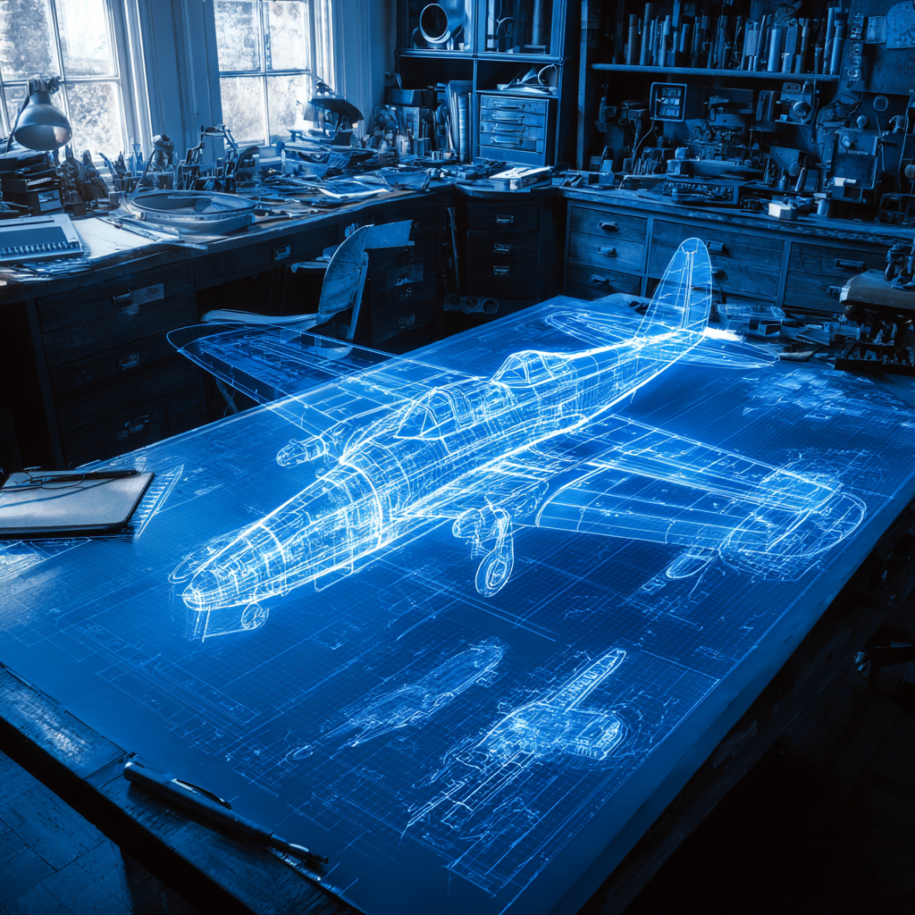
How to Build an Aircraft Model by Converting 3D-Scanned STL Files into Functional 3D STEP Files
This in-depth guide will teach engineers how to use 3D-scanned aircraft files and transform them into manufacturable 3D STEP files with fewer mistakes.