3D CAD – A Primer


3D CAD – A Primer
3D CAD comes in different “flavors” that are used differently and that require the CAD technicians to design their virtual components in a different manner for each. Here is a list of the types of 3D CAD this article discusses:
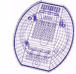
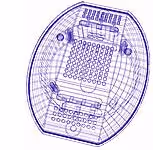
- 3D wireframe
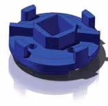
- 3D “dumb” solids
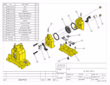
- 3D parametric solid modeling
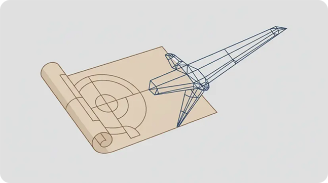
3D wireframe, while not often used today, is worth mentioning simply because the approach to 3D wireframe is similar to that used in 2D CAD systems. Persons familiar with 2D CAD will understand these concepts: (1) each line has to be manually inserted into the drawing; (2) the final product has no mass properties associated with it; (3) the final product cannot have features added directly to it. The wireframe model is used to make the final engineering drawing views.
3D “dumb” solids, also not often used today, are created in ways similar to manipulations of real-world objects. Basic three-dimensional geometric forms, such as prisms, cylinders, spheres, etc. have solid volumes added or subtracted from them, as if assembling or cutting real-world objects. These models allow for easy two-dimensional projected views to be generated. Basic 3D solids don’t usually include tools to easily allow motion of components, set limits to their motion, or identify interference between components.
3D parametric solid modeling requires the operator to use what is referred to as “design intent”. Design intent simply means that the purpose of the design is taken into account when creating the model. How the design will be used dictates the relationship between features in parts and parts assemblies. If a feature is intended to be located from the center of the part, the CAD technician needs to locate it from the center of the model, just as it will be in real life. This is very different from “dumb” models, where the feature could be located from some more convenient area in the 3D drawing, so it would “look” correct, but, not, in fact, represent the real world.
Parametric solids require the operator to consider the consequences of his actions carefully because the objects and features created are adjustable. And just as in real life, moving a feature even a fraction of an inch may adversely affect other features, depending on how the original part was designed.
Parametric 3D solid modeling provides a virtual image of the design that can be rotated, manipulated, retrieved and modified at any time.
About 3D CAD Services
CAD / CAM Services, Inc. employees professional engineers and architects who are experienced in all aspects of the 3D CAD. We work with architectural drawings, manufacturing drawings, aerospace drawings, defense department drawings and any other types you may have. When you need any work on a 3D CAD file, we can do it fast and at a very low cost. We can convert hardcopy documents into any 3D CAD program such as Revit, Solid Works, CATIA, and other 3D programs.

Recent Posts

How to Choose a CAD Outsourcing Partner for Aerospace That Preserves Your Design Intent
Learn how to choose a CAD outsourcing partner for aerospace. Avoid costly data translation errors. 35+ years of experience guide your selection.

6 Easy Steps to Convert a 2D to 3D Model Using SolidWorks
Take a Look at Our Case Studies! Solidworks as a platform offers two main 2D to 3D pathways; drawing from scratch and remodeling existing ‘.DWG’ and ‘.DXF’ files as 3D models. The functionality of importing an existing 2D drawing and upgrading it into a...

Tips for Picking the Perfect 3D CAD Viewer for Your Needs
This guide will teach you about 3D CAD viewers and outline considerations to make before picking the right one. We review 5 options and pick a clear winner.