Reverse Engineering a Legacy Rotor Shaft
Problem Definition
A client needed a replacement rotor shaft for industrial equipment. Original CAD files, drawings, and specifications were unavailable. The shaft featured complex geometry:
- stepped diameters,
- bearing journals,
- keyways,
- seal interfaces,
all critical to balance and fatigue life.
Manual measurement tools couldn’t capture the geometry, and wear had altered critical surfaces. The goal was to create an accurate, parametric 3D CAD model for manufacturing, redesign, and future production.
Reverse Engineering Process
The rotor shaft was scanned with a laser scanner. Multiple scan orientations captured full geometry, including journals, fillets, keyways, and end features. Scan data was merged into a watertight point cloud and mesh model.
We created a high-resolution mesh and imported into Geomagic Design X CAD software. Our engineers reconstructed features using datum axes to produce a parametric CAD geometry. Worn areas were rebuilt using best-fit geometry, while parametric features were added for diameters, fillets, and mounting interfaces.
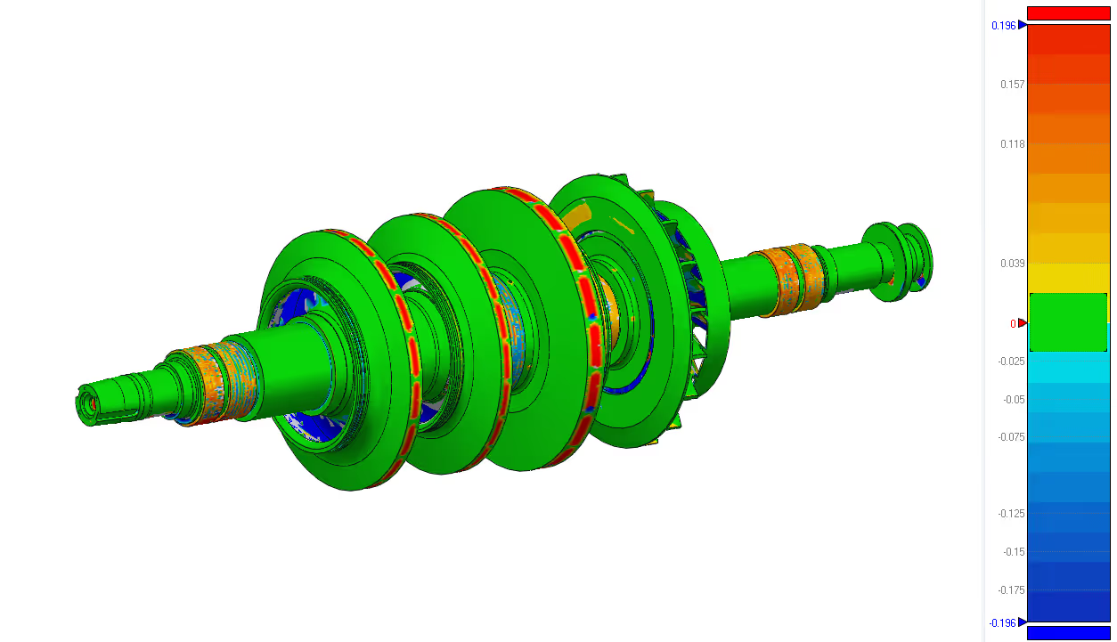
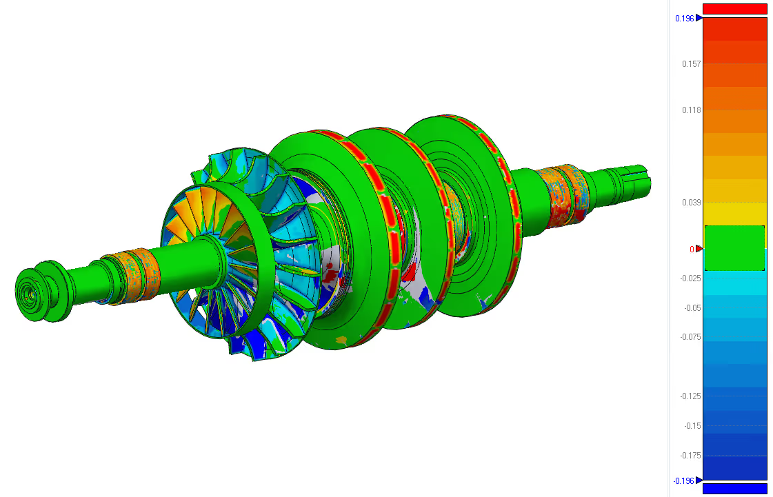
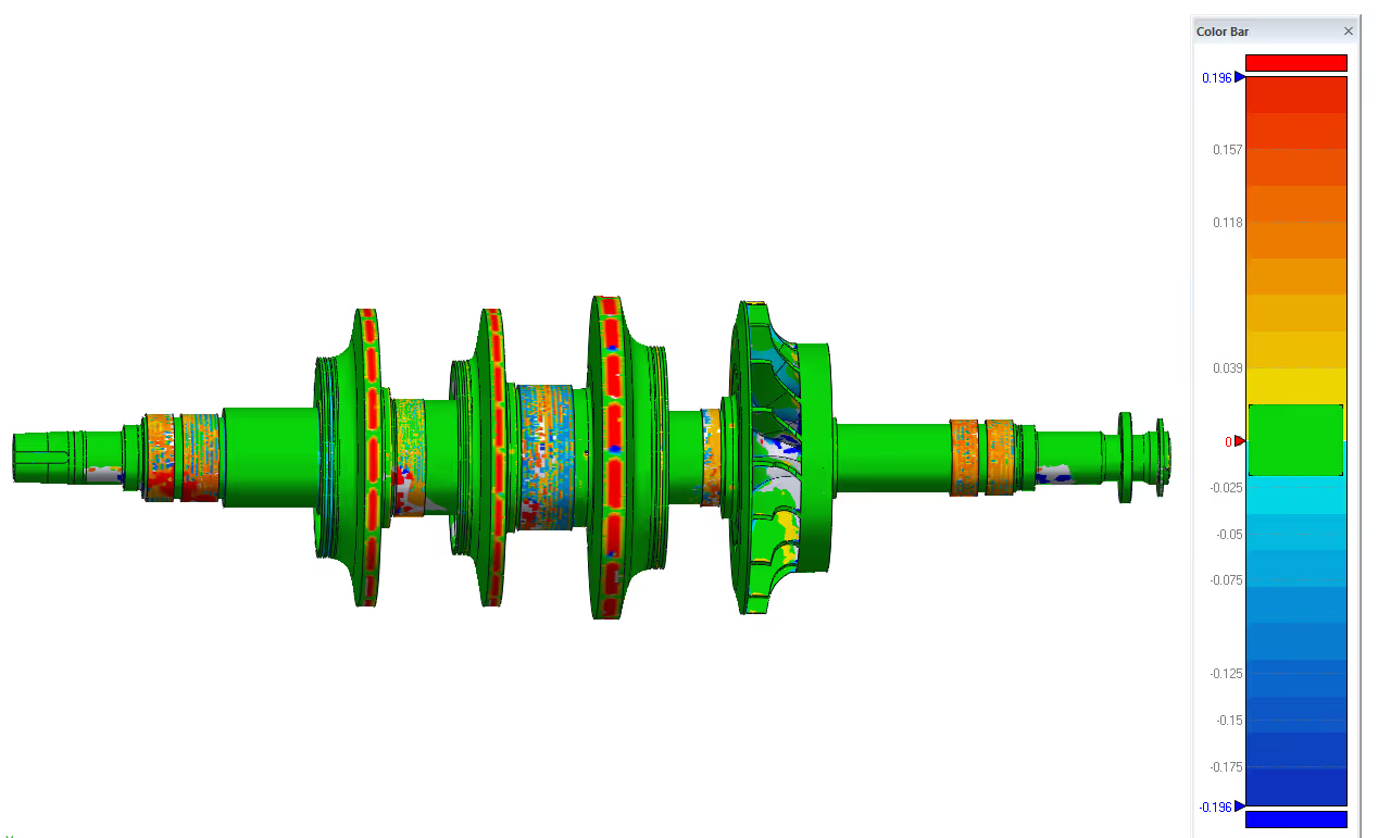
The CAD model was validated by comparing it to scan data. We ensured to meet accuracy of journal diameters and shoulder locations.
Engineering Challenges
Challenges included:
- surface wear on bearing journals,
- scan noise from reflective surfaces,
- fillet reconstruction,
- maintaining tight geometrical tolerances for dynamic performance.
Final Outcome
The project produced a fully parametric CAD model of the rotor shaft in Geomagic Design X. The original geometry is ready for CNC machining, redesign, and FEA. The digital model supports future changes, quality control, and maintenance, while reducing reliance on manual measurements and trial machining. All these achieved while preserving original design intent.