Engine Housing Reverse Engineering
Reverse engineering is a method for creating a 3D virtual model from a physical part. Engineers use this model in 3D computer-aided design (CAD) and similar processes. This means measuring the object and creating a 3D model.
In this case study, we aimed to create a full digital model of an engine casing. This casing had no current CAD files, outdated drawings, and undocumented shapes because of years of use and part changes. Engineers couldn’t analyze finite element behavior, check tolerances, or redesign component interfaces without a precise digital model.
How We Executed the Reverse Engineering Process
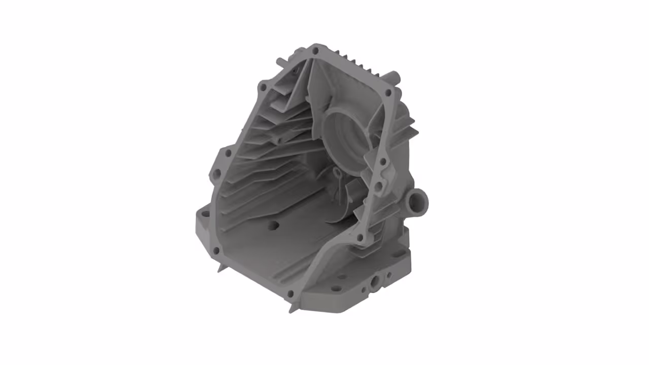
The first step in any successful reverse engineering workflow is data capture. For this, we used 3D laser scanning. This method captures the shapes of small metal features without touching them.
To improve the digital capture, we added alignment markers. We also scanned multiple times to capture complex features like ribs, internal shapes, bolt holes, and structural recesses.
After we completed the scanning, we cleaned the raw point cloud. We removed noise and reflections from shiny metal surfaces. Then, we combined overlapping scans into one 3D dataset.
At this stage, CAD software becomes the platform where real engineering begins. We used special reverse engineering software in CAD systems. We rebuilt the geometry by tracing the mesh. Then, we converted it into parametric surfaces and solid features.
Challenges in Reverse Engineering a Complex CAD Model
Engine casings are very difficult to recreate due to their complex CAD model geometry. Internal voids, deep pockets, and overlapping surfaces make simple measurement techniques impractical.
Converting the point cloud data into meaningful design features is another common challenge. A CAD model is different from a mesh. A mesh shows the surface's appearance. In contrast, a CAD model contains design intent, parametric constraints, and features that users can edit.
What the Final Model Delivered
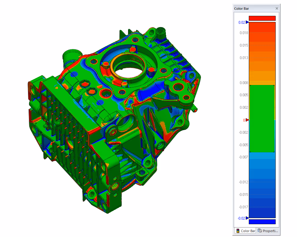
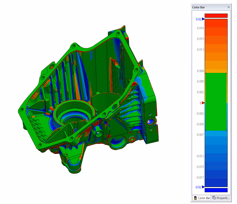
This process created a high-quality and affordable digital model that matched the real shape of the engine casing. Having completed our project to rebuild geometry in CAD, the model is now ready for various engineering tasks.
The client received a fully documented digital engine casing that aligned with current conditions. The new digital CAD model supports:
- Manufacturing and fabrication workflows
- Redesign and updates without guesswork
- Stress and tolerance analysis
- Quality control and inspection workflows
- Integration with 3D printing or CNC production
For additional information on this process, check out our gallery and FAQ pages.