AFT Closure Beam Assembly – Aerospace Structure
Project Background
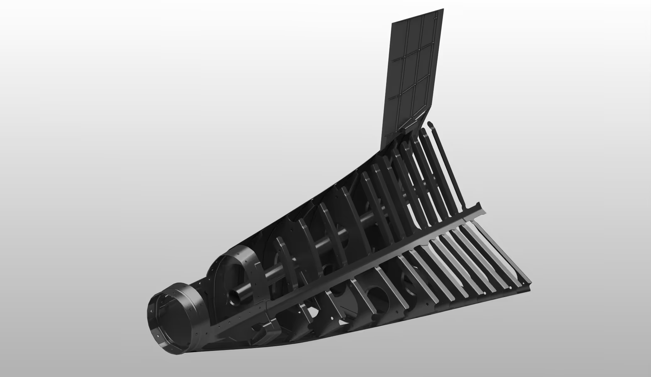
Our team received the job of creating a detailed 3D CAD model of the AFT closure beam. This beam is an important part of the back fuselage. It helps with load transfer and connects with skins, bulkheads, and closure parts.
This project involved sheet metal parts for aerospace, like flanges, joggles, curved skins, and stiffeners. All these needed to fit perfectly in the aircraft’s coordinate system during design. We used Siemens NX CAD modeling to deliver a precise, fabrication-ready aerospace CAD model. This model would support aircraft parts production, aerospace manufacturing, and ongoing product development.
Drawing Alignment in 3D
First, we chose consistent datums across drawing sets to anchor placement. Where drawings lacked scale, we referenced known part dimensions to derive scale factors, then imported drawing curves into NX.
We placed each drawing in its correct 3D plane and overlaid adjacent views. Iterative alignment checks ensured consistency, eliminated mismatches, and verified that projections nested properly.
Sheet Metal Part Modeling
We used Siemens NX’s sheet metal features to create flanges, joggles, bends, and reliefs. We applied the right K-factors, bend tables, and corner/edge rules. We also validated that each component could flatten without distortion or self-intersection.
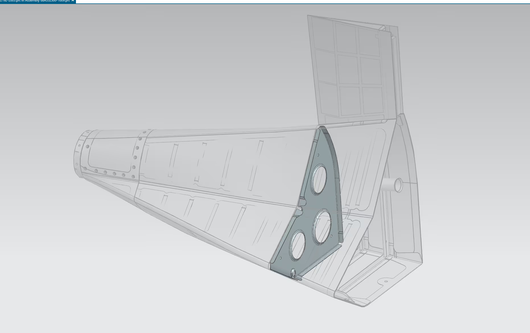
Assembly Integration and Clash Resolution
We added parts to the full assembly using alignment, offset, or coincident constraints. These constraints follow the drawing relationships, like skin to beam flange or stiffener to bulkhead. After each major insertion, we ran NX’s interference checks.
Our iterative feedback loop allowed us to eliminate overlaps while staying true to the geometrical references.
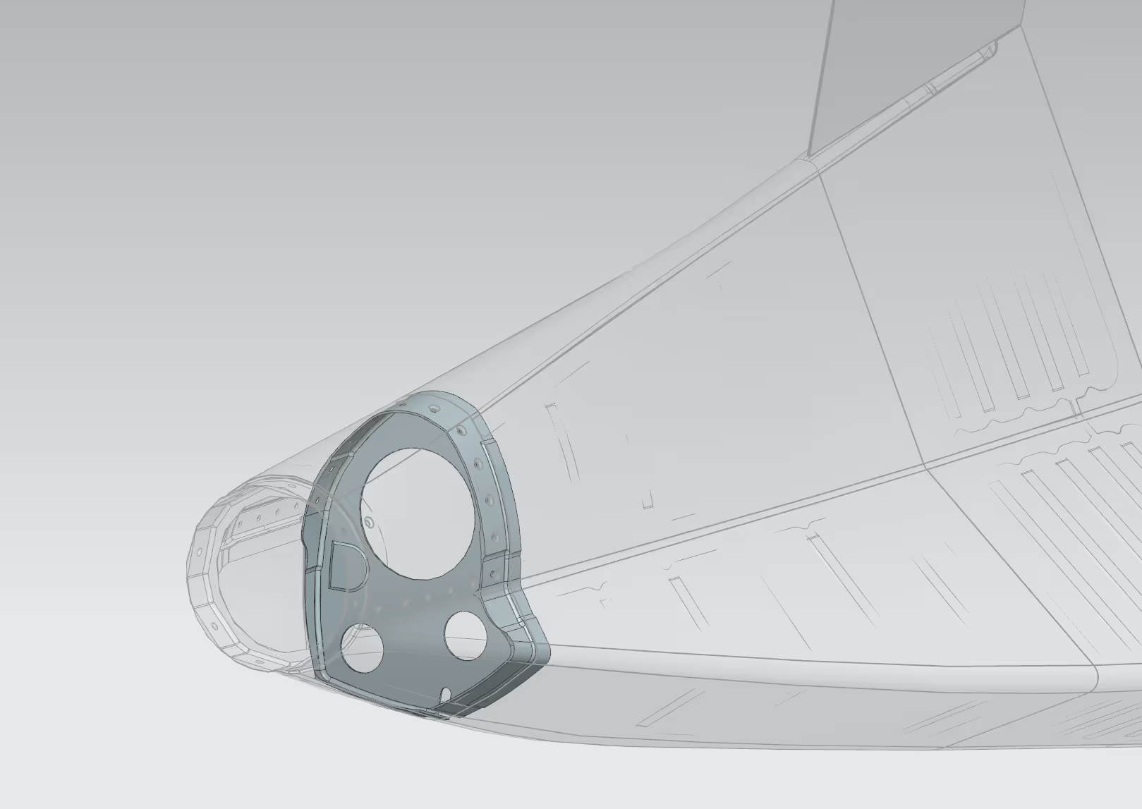
Validation and Fabrication Output
Once the full assembly was in place, we did internal checks. We checked section cuts, flange continuity, thickness uniformity, and mating surfaces. Next, we flattened and examined each sheet metal part for shape or extension issues.
We exported flat patterns and handed them off for CNC machining, ready for parts manufacturing. After we checked the sheet metal parts and exported the flat patterns, we sent important brackets and fittings to CNC machining.
Results and Benefits
Finally, we delivered a robust Siemens NX CAD model of the AFT closure beam with full feature history. A well-made CAD assembly sped up teamwork across different fields. It allowed for more design changes before starting production.
The end product facilitated integration with 3D printing, simulation, tooling design, and broader product development in the aerospace industry.