6 Easy Steps to Convert a 2D to 3D Model Using SolidWorks
Take a Look at Our Case Studies!
Solidworks as a platform offers two main 2D to 3D pathways; drawing from scratch and remodeling existing ‘.DWG’ and ‘.DXF’ files as 3D models. The functionality of importing an existing 2D drawing and upgrading it into a fully-fledged 3D model is widely utilized. As CAD has increased in complexity, it has become pivotal to generative design to update previous designs.
There are three key stages to be completed; the import wizard, the ‘sketch arrangement’ stage, and the extrusion to create a 3D model. The ‘sketch arrangement’ is merely pertaining to the several steps that decide where the geometry lies concerning the planes and the origins.
This process begins with opening the original files, as usual. Immediately following this, the ‘import wizard’ dialog box opens, selecting the “Import to a new part as 2D sketch” option is the correct method to complete the 2D to 3D conversion.
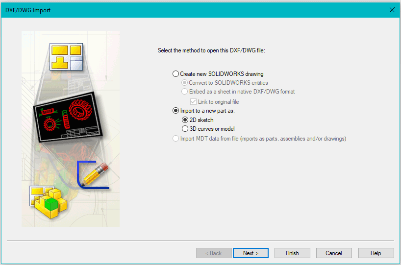
SolidWorks Import Wizard
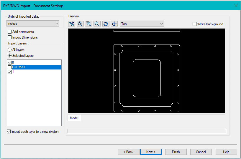
The subsequent stage is the ‘document settings’ page, allowing more complex adaptations of the drawing. This includes individual layer selection, allowing intricate design choices, often all layers are included as specific features can be easily omitted.
In addition to layer selection, the user can add constraints, import dimensions, and generally edit the design at this stage. It is worth noting if all layers are selected, measurements are imported, and the constraints are correct, then the drawing is likely to be complete and ready for conversion, although there are a few stages left.
Pressing next leads us to the ‘drawing layer mapping’ options menu, which is virtually there to help ensure the design is a complete and functional sketch. This is fundamental to a successful 2D to 3D conversion. The features include merging points at a set radius, connecting overlapping entities, repairing sketches, and defining the sketches’ origin.
Drawing layer mapping menu
Of these features, the merge points and merge overlapping entities are especially useful during this process. By selecting to merge points at a distance of 0.001, this ensures Solid Works will connect any geometry intended to join.
This menu also contains the useful, if awkward, ‘Remove Entities’ function. This allows for the deletion of specific sketch entities, where they can be selected individually in the preview box. Generally, it can be more practical and intuitive to leave all the entities until it is a part file and then proceeding to edit the design.
This concludes the ‘Import Wizard’ stage, pressing finish results in a 2-dimensional sketch formed as a part document. It should now open in SolidWorks, along with the 2D to 3D tools.
The next stage is imperative to further use this part, in assemblies, or for manufacture, as this is where the sketch’s orientation is defined. This begins with the front sketch, a simple drag highlight, and choosing the front sketch button, laying the selected geometry on the front plane.
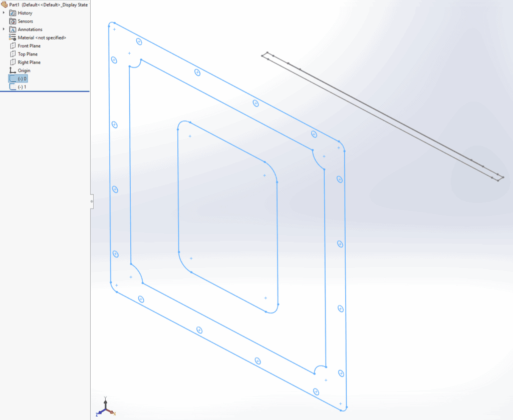
Sketch selection step
This process is repeated for the top sketch and the right sketch, which is necessary to generate a full three-dimensional model. Now we have defined the drawing’s orientation, and we need to relate these both to the origin and each other.
This involves using the ‘align sketch’ tool, selecting the feature we want to align to the origin, usually a point somewhere on one of the views. This positions the sketch within the plane, leaving us able to use the same tool in order to align the different views in relation to each other.
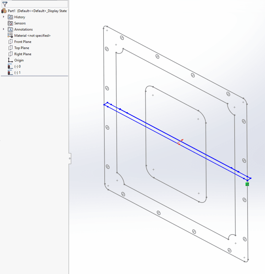
Align sketch tool
Concluding the ‘sketch arrangement’ stage, each sketch can be aligned to a defining plane, which is essential to allow any redesigning or editing of the model.
This brings us to the third and final stage, extrusion. During a 2D to 3D conversion, the extrusion tool is slightly different, but by selecting the ‘up to vertex’ from the property manager and then choosing from whichever sketch defines the thickness.
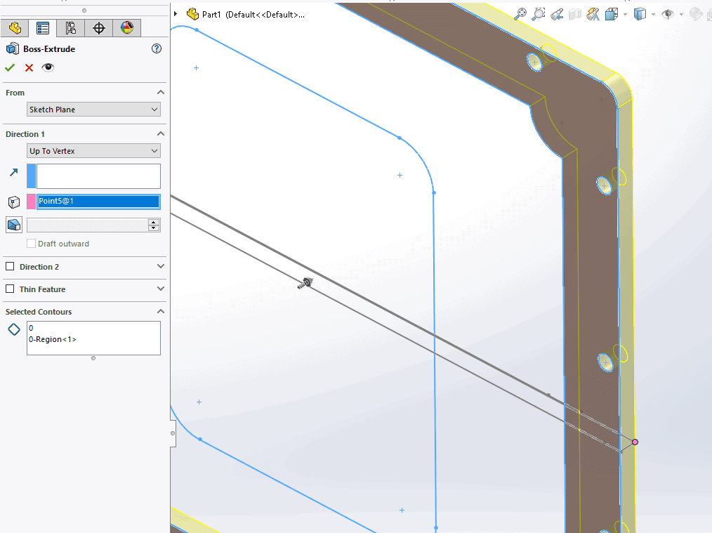
Vertex selection tool
Before completing this action, it is worth double-checking that every feature we want to extrude is selected. It is best practice to use ‘Contour Selection’ to select them all, making sure to grab any intricate features.
To conclude, this feature of SolidWorks is endlessly useful; its central uses are twofold. Primarily it is excellent for modernization, taking existing 2D designs and quickly developing them into fully functional 3D models. Secondly, for generative design, where specific engineering processes can be very lengthy, the most recent software is key to developing market-leading products.
Essentially, for an established engineering firm, with a catalog of existing designs, there is a simple solution to stay updated by using SolidWorks purpose-built tools.
Voila your part is officially converted from 2D to 3D!
Recent Posts


Outsourcing Engineering Services – Pros and Cons
This guide gives an in-depth look at the pros and cons associated with outsourcing engineering services, whether it’s a portion of the project or the whole thing.

10 Benefits of Outsourcing Your Drafting Project
This guide will teach you the function and importance of as-built drawings. You’ll also learn the power of outsourcing your as-built drawing services.

Large Format Scanning — What You Need to Know
This intro-level guide will walk you through the basics of large format scanning, including how they work and how it can benefit any engineering department.