Case Studies
CLIENT’S INTRODUCTION
Our client, a multinational firm, is a leading maintenance company, providing maintenance services of all the machinery equipment, is often confronted with an issue of non-availability of machine parts, either due to outdated machinery or a certain modification from the stock part may be required for performance improvement, this leads them to have the specific part remanufactured. For remanufacturing they require a design and CAD / CAM services is the firm they contact to reverse engineer any design. CAD / CAM services is a top-notch firm, providing services in reverse engineering, 3D Scanning, CAD conversion, 3D modelling, Designing and manufacturing codes.
CASE
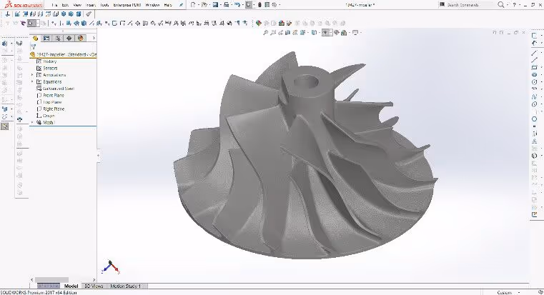
Once our client faced an issue, which required them to remanufacture an impeller. They decided to reverse engineer the impeller, by scanning it, using a laser scanner and then to convert it into a CAD model, for generating G-codes for manufacturing on a CNC machine. So, they performed a laser scan of the impeller, but a distorted surface was generated, due to complex blade surfaces, which geometrically reflected the laser beam. Because laser scanning works on the principle of reflected rays of light, the features need to be in the line of sight of the scanner to receive and reflect rays of light effectively, but the impeller possessed an intricate geometry which made it difficult to reverse engineer.
ERRORS ASSOCIATED WITH LASER SCAN
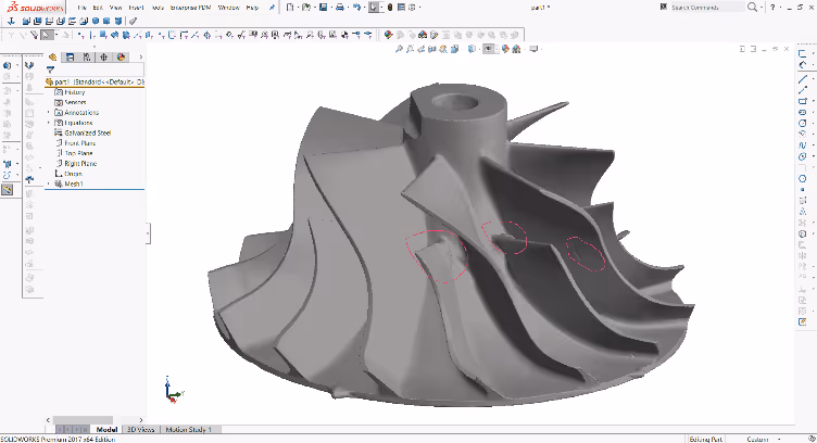
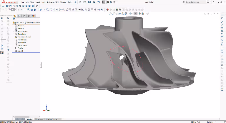
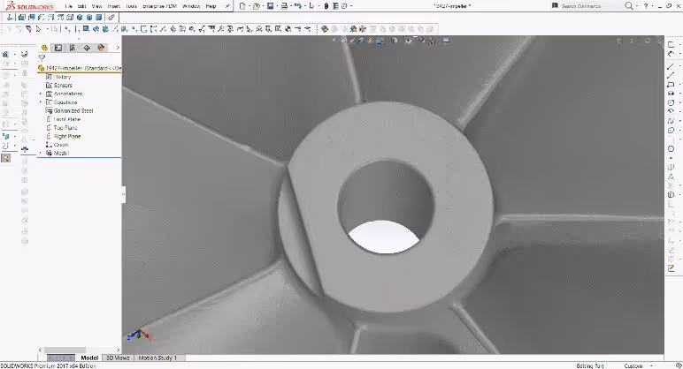
There were numerous errors associated with the laser scanned model, making it impossible to reverse engineer accurately. Most common being the non-uniform profile, convexity on the surfaces and existence of holes on the surfaces, as shown in figure 2 and figure 3 respectively. The process to fix or repair this 3D scanned model was very cumbersome and, in some cases, it required approximation of the lost details. Which in other words meant a compromise on accuracy of reverse engineered model.
CHALLENGE
To avoid a loss in accuracy, our client decided to hire our services. Our client wanted us to reverse engineer the impeller to generate a 3D cad model to be used for CAM. We proposed two ways to cater the difficulty being faced by our client, either the impeller was to be designed from scratch using the set of available boundary and working conditions or to perform a scan using another 3d scanning technique known as the Computed Tomogram scan. It was possible for us to redesign the impeller from scratch, because of our professional design team, but our client insisted to reverse engineer the same part, for whatever reason it might be.
Following were the milestones to be achieved by our team
- Reverse Engineer the impeller
- Optimize the model for CAM
SOLUTION
We decided to reverse engineer the impeller using CT scan, after generation of the scanned model we had to remodel the surface using minimal features in feature tree to optimize the model for CAM.
WHY CT SCANNING?
CT scan model was selected because of the following advantages it possesses over the laser scanning method.
- CT scans internal geometry of model effectively because it scans the object by the amount of radiation absorbed by the various parts of the object, whereas laser scanning scans using reflect rays of light. So, a model should be cut to bring internal features in the line of sight in case of laser scanning.
- Scan based on laser technology distorts the physical geometry of model because of interference on the complicate region which makes a quite difficult perception of a real object.
- No effect of colour and lightning of object on 3D scanning result.
CT SCAN
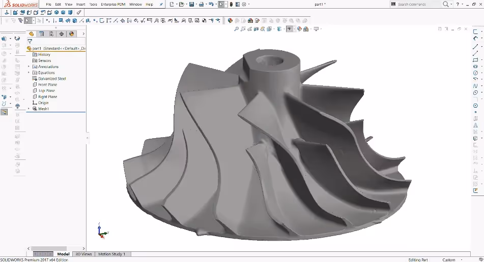
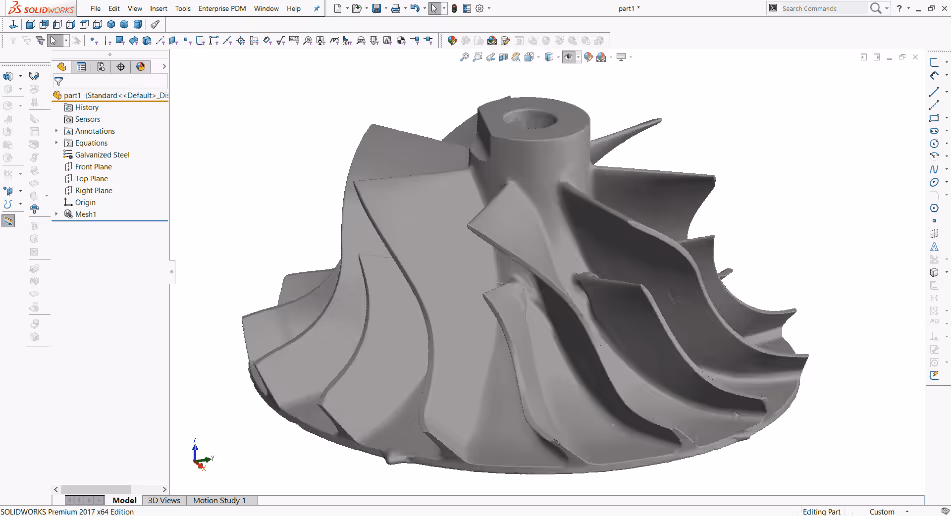
Considering the advantages described above, our 3D scanning team scanned the impeller with a CT scanner. They converted the 3D points data into a SolidWorks mesh-based model. CT scanned model preserved the intricate profiles, neither the bulging surfaces nor the holes were observed. It was possible to find out the whole topography of the model including internal areas with a quite high precision equal to 0.00025 in.
OPTIMIZATION FOR CNC
Our CAD conversion team was assigned the task to optimize the model for CNC machining. They generated the surfaces mating with the scanned mesh surfaces, the model comprising of the generated surfaces could be used efficiently for CNC machining. The optimization reduced the CNC mill time by 25%. Optimized CNC model was delivered to the client.
CONCLUSION
That’s how we provide our clients’ professional services in reverse engineering, 3D scanning, 3D modelling, CAD / CAM. So, if you need to reverse engineer any product or require anything regarding CAD / CAM, get a quote from CAD / CAM services by visiting https://www.cadcam.org.